-20-
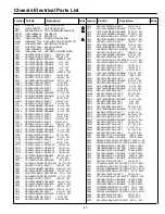
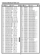
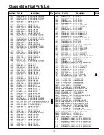
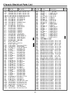
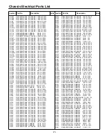
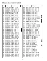
Chassis Electrical Parts List
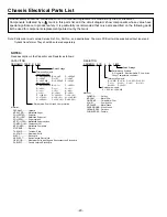
Product safety should be considered when a component replacement is made in any area of a receiver.
Components indicated by a
!
mark in this parts list and the circuit diagram show components whose value have
special significance to product safety. It is particularly recommended that only parts specified on the following parts
list be used for components replacement pointed out by the mark.
Note: Parts order must contain Service Ref. No., Part No., and descriptions. The main PCB unit will be supplied without tuner and
flyback transformer. They should be ordered separately.
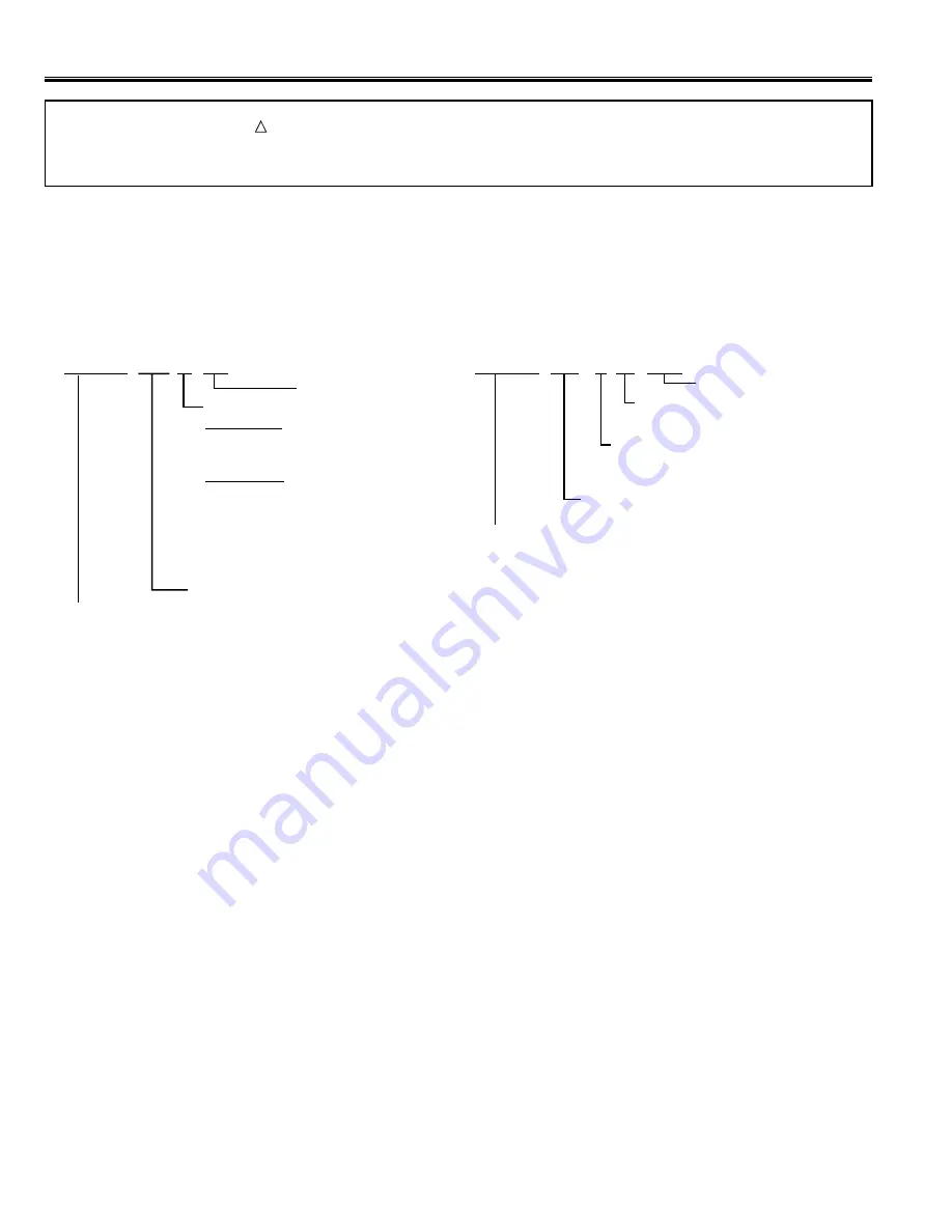
Read description in the Capacitor and Resistor as follows:
CAPACITOR
CERAMIC 100P K 50V
Rated Voltage
Tolerance Symbols:
Less than 10pF
A : Not specified B :
±
0.1pF
C :
±
0.25pF
D :
±
0.5pF
F :
±
1PF
G :
±
2pF
R :
±
0.25-0pF
S :
±
0-0.25pF E : +0-1pF
More than 10pF
A : Not specified B :
±
0.1%
C :
±
0.25%
D :
±
0.5%
F :
±
1%
G :
±
2%
H :
±
3%
J :
±
5%
K :
±
10%
L :
±
15%
M :
±
20%
N :
±
30%
P : +100-0%
Q : +30-10% T : +50-10%
U : +75-10%
V : +20-10% W : +100-10%
X : +40-20%
Y : +150-10% Z : +80-20%
Rated value: P=pico farad, U=micro farad
Material:
CERAMIC...........Ceramic
MT-PAPER.........Metallized Paper
POLYESTER......Polyester
MT-POLYEST.....Metallized Polyester
POLYPRO.......... Polypropylene
MT-POLYPRO....Metallized Polypropylene
COMPO FILM.....Composite film
MT-COMPO........Metallized Composite
STYRENE...........Styrene
TA-SOLID...........Tantalum Solid
AL-SOLID........... Aluminium Solid
ELECT................Electrolytic
NP-ELECT..........Non-polarised Electrolytic
OS-SOLID.......... Aluminium Solid with Organic Semiconductive Electrolytic
DL-ELECT.......... Double Layered Electrolytic
RESISTOR
CARBON 4.7K J A 1/4W
Rated Wattage
Performance Symbols:
A: General B: Non flammable Z: Low noise
Other: Temperature coefficient
Tolerance Symbols:
A:
±
0.05% B:
±
0.1% C:
±
0.25% D:
±
0.5%
F:
±
1% G:
±
2% J:
±
5% K:
±
10%
M:
±
20% P: +5-15%
Rated value, ohms:
K: 1,000, M: 1,000,000
Material:
CARBON........... Carbon
MT-FILM............ Metal Film
OXIDE-MT......... Oxide Metal Film
SOLID................ Composition
MT-GLAZE......... Metal Glaze
WIRE WOUND...Wire Wound
CERAMIC RES.. Ceramic
FUSIBLE RES....Fusible
NOTES:
-20-
Summary of Contents for 113020208
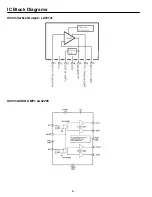
Page 4: ...IC Block Diagrams IC601 POWER SUPPLY IC STRW6754 FUNCTIONAL BLOCK DIAGRAM ...
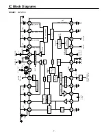
Page 5: ...IC Block Diagrams IC201 IF Video Chroma Def CPU LA76113 ...
Page 6: ... IC Block Diagrams IC501 Vertical Output LA78141 IC001 AUDIO AMP LA42205 ...
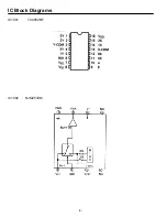
Page 8: ... IC Block Diagrams IC1002 NJM2533M IC1001 TC4052BF ...
Page 28: ...Feb 2009 ...

