background image

25

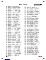
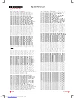
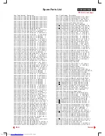
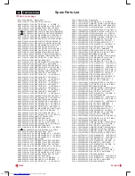
109P2 GS3 CM25

PCB (B, C)

1101 F1

2579 E7

3421 E8

3633 C5

6540 D3

9143 E5

9535 A7

2123 G4

3624 D6

1102 G2

2586 G8

3422 E8

3634 C5

6541 D5

9144 F5

9541 E7

2125 G5

3626 D6

1103 G1

2587 G7

3424 E8

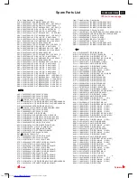
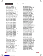
3653 C1

6542 D3

9148 F6

9542 E6

2154 F5

3628 D6

1130 E2

2588 G7

3426 D8

3658 B1

6543 D4

9311 B8

9543 G7

2155 F6

3630 D6

1131 E1

2589 G7

3427 D8

3659 B1

6544 B3

9312 A8

9544 E6

2161 E1

3632 D6

1134 E1

2601 D3

3428 F9

3671 B2

6545 A3

9314 A8

9546 D2

2162 G5

3652 B1

1301 B9

2602 C4

3432 E9

3672 C3

6566 F8

9315 A8

9547 B1

2302 B9

3654 B1

1302 D1

2603 D3

3433 E9

3674 C1

6567 F7

9335 B8

9548 E2

2309 B9

3655 B1

1303 D1

2604 C3

3441 F8

3675 C1

6573 F6

9336 B8

9549 E6

2310 B8

3656 B1

1306 G9

2605 C3

3442 F9

3676 D1

6601 C3

9337 B8

9601 C3

2313 B9

3657 B1

1311 A9

2608 C3

3443 E9

3677 C1

6602 D2

9341 B7

9901 D6

2314 B9

3660 C1

1501 B5

2611 D2

3450 F9

3678 C1

6603 C3

9342 B7

9902 E8

2315 B8

3661 C1

1502 G7

2613 D2

3456 F8

3679 C1

6621 D5

9343 B7

9903 E8

2337 A9

3662 C1

2102 F2

2620 B6

3458 A3

3680 C1

6622 D5

9344 B7

9904 G8

2338 A9

3663 B1

2103 F3

2621 C6

3462 E7

3681 C1

6651 C1

9345 B7

9905 G6

2345 D1

3664 D1

2104 G3

2622 C6

3465 D9

3682 A1

6652 B1

9346 B7

9906 D8

2351 D1

3665 D1

2111 G5

2623 C6

3466 D9

3683 B1

6655 D1

9347 B7

9908 B8

2352 D1

3666 D1

2112 G5

2624 C6

3468 F9

3684 A1

6671 C2

9401 E6

9909 A8

2353 D1

3667 D1

2115 G6

2625 C5

3469 F9

3685 A1

6672 C1

9403 C1

9911 D7

2391 C7

3668 C1

2116 F5

2626 C5

3470 F8

3689 A7

6673 C1

9404 C1

9912 D7

2392 D8

3673 A1

2121 G4

2627 C5

3471 F9

3690 A8

6674 C2

9405 C1

9913 D7

2424 E7

3686 A1

2122 G4

2632 C6

3472 F8

3691 A1

6691 A1

9406 F9

9914 D7

2442 E9

3687 A1

2124 G3

2635 C5

3473 F7

3692 A1

7111 G6

9407 B1

9915 D7

2443 E9

3688 A1

2127 E1

2636 C5

3474 F8

3693 A1

7121 G4

9408 A1

9916 D7

2444 E9

3700 C1

2128 F2

2651 B1

3475 F7

3694 A1

7130 F5

9411 A7

9917 D6

2462 E7

5354 D1

2129 F2

2655 B1

3476 F8

3695 A1

7140 E5

9412 D1

9918 D6

2464 E7

5355 E1

2130 F3

2656 C1

3493 B8

3696 A2

7143 F6

9413 C4

9919 C7

2492 B8

6114 G4

2131 E2

2659 D1

3495 B8

3697 A1

7144 F5

9414 A4

9920 C7

2493 B8

6160 E2

2133 E3

2671 C3

3501 B7

3698 A1

7146 E5

9416 D5

9921 A5

2545 E7

6162 E5

2134 E4

2673 C1

3502 B6

4120 G3

7151 F6

9417 D2

9922 D7

2546 E7

6301 B8

2135 E3

2682 D2

3503 A7

4121 G4

7155 F6

9420 D2

9923 E3

2612 D2

6391 C8

2137 E4

2683 C2

3504 A7

4301 E7

7161 E1

9421 D2

9924 D6

2652 B1

6392 C8

2139 E4

2684 A1

3505 B7

4302 D6

7301 B8

9422 E2

9925 E8

2653 B1

6423 F9

2142 F6

2685 A1

3506 A5

4601 D1

7336 A9

9426 C5

9926 E4

2654 B1

6463 D9

2143 E6

2686 B1

3507 A5

4602 A5

7351 D1

9427 C5

9927 D2

2657 C1

6653 C1

2144 F5

2691 A1

3515 B5

4603 D3

7363 E7

9428 C6

9928 E2

2658 C1

6654 D1

2145 E5

2693 A1

3516 B4

4604 D6

7364 E6

9429 C6

9929 E4

2660 C1

7141 E4

2151 F5

2694 A1

3517 B6

4606 E7

7401 D9

9430 C6

9930 F6

2661 C1

7147 E5

2156 F2

3103 G1

3518 B6

5101 F2

7404 D9

9431 C6

9931 E4

2672 C1

7148 E5

2160 E1

3104 G4

3519 A6

5102 G2

7421 E9

9435 B6

9932 E3

2681 C1

7162 G5

2304 C9

3105 G3

3520 B6

5103 F2

7422 F9

9436 B6

9933 E2

3124 G5

7163 G5

2305 C9

3106 G3

3521 A6

5104 G4

7423 E9

9439 C7

9934 E4

3140 E4

7302 D9

2306 A8

3107 G3

3522 A6

5130 F4

7425 F8

9440 C7

9935 D6

3143 E4

7303 D9

2311 B9

3108 G3

3523 A7

5301 C8

7426 F8

9441 C7

9936 E5

3144 F5

7391 C8

2312 B9

3109 G2

3524 A6

5302 A9

7461 E7

9442 C7

9937 D5

3148 F5

7392 D8

2316 B9

3111 G6

3525 A6

5351 D1

7462 E9

9443 C7

9938 E6

3151 F5

7402 D8

2317 B8

3112 E3

3528 A7

5353 D1

7463 F9

9444 C7

9939 D5

3153 F5

7424 F9

2336 A9

3115 G5

3531 A7

5501 B6

7464 F9

9445 C7

9941 A4

3155 F6

7427 F9

2354 E1

3121 G4

3541 D5

5502 A5

7465 F8

9446 C7

9942 D5

3156 F6

7466 C9

2355 D2

3123 F3

3542 D3

5503 B5

7491 B8

9447 B7

9944 E5

3303 B9

7501 B6

2361 E7

3125 G5

3544 D4

5504 C5

7502 A5

9449 B7

9945 E6

3307 B8

7544 A7

2362 E6

3127 F1

3545 B4

5505 A5

7503 A6

9450 F8

9946 E5

3308 B8

7566 F8

2401 D8

3128 E1

3546 D5

5542 D4

7504 A6

9453 C8

9947 E5

3310 B9

7602 D2

2421 E8

3141 E4

3551 B3

5543 B3

7505 A7

9454 D8

9951 A5

3316 B9

7603 D2

2422 E8

3142 F5

3552 A3

5544 C3

7541 D3

9455 B8

9952 A1

3318 B8

7627 B6

2423 E8

3145 F5

3553 B3

5545 B4

7542 B3

9456 D9

9955 D1

3323 A9

7628 C6

2425 E8

3146 E5

3554 A3

5601 C4

7543 B3

9457 C8

3324 B8

7629 C6

2426 E8

3147 F5

3566 F8

5670 D1

7545 A7

9458 D8

3325 B8

7630 C6

2431 D9

3152 F5

3569 E6

5671 B2

7567 F7

9459 C9

3332 B8

7631 C5

2432 E9

3154 F5

3570 F7

5672 D2

7586 G8

9460 C9

3333 A9

7632 C5

2433 E9

3157 F6

3571 F7

6101 G3

7587 G7

9461 C7

3339 B8

7633 C5

2434 E9

3160 E2

3572 F7

6104 G4

7588 G7

9462 B9

3340 B8

7653 D1

2435 E9

3161 E1

3573 F6

6109 G4

7601 D2

9463 C9

3341 B8

7654 C1

2440 F9

3162 E1

3574 G7

6111 F6

7620 B6

9464 C7

3342 B8

2441 E9

3163 G4

3576 F7

6112 G5

7621 C6

9466 A9

3351 D1

2445 F9

3167 E2

3577 E6

6113 G5

7622 D6

9469 A8

3393 D8

2446 F9

3301 C9

3578 F7

6115 G5

7651 C1

9476 C7

3394 D8

2456 F8

3302 B9

3579 F7

6116 F5

7652 B1

9477 C8

3395 D8

2461 F7

3304 C9

3580 F7

6125 G5

7671 C1

9478 B9

3396 D8

2463 F9

3305 C9

3581 B5

6131 E3

7672 C1

9486 C9

3401 D8

2491 B8

3306 C9

3582 F7

6132 E5

7673 C2

9487 C8

3402 D8

2501 B7

3309 C9

3586 F8

6133 E3

7674 A1

9488 C8

3403 E9

2502 A7

3311 B9

3587 G8

6134 E4

7675 D2

9491 C8

3405 C8

2503 A7

3312 A9

3588 F8

6135 E3

8001 C8

9493 C8

3423 E8

2506 B4

3313 A9

3589 G8

6137 E4

8002 A8

9501 C8

3425 E7

2507 B5

3314 A8

3590 G8

6139 F5

8003 E6

9502 D8

3429 F9

2508 B4

3315 A8

3591 G7

6140 E5

8004 A8

9504 C8

3430 F9

2509 A4

3317 D8

3592 G7

6144 F5

8101 G3

9505 E4

3431 E9

2515 B5

3319 A9

3593 G7

6145 E5

8102 F3

9506 D3

3434 E9

2516 B6

3320 A8

3594 B7

6152 F5

8103 F2

9508 D9

3444 E9

2517 A6

3321 A8

3601 D3

6161 G5

8104 G2

9509 D9

3445 E9

2518 A7

3322 B8

3602 C3

6302 A8

8105 G2

9511 E7

3446 E9

2519 A6

3326 D8

3603 C3

6421 F9

8106 F5

9512 E7

3451 F9

2520 A6

3327 C8

3604 C3

6422 E8

8301 A9

9513 E8

3457 F8

2542 D3

3328 A9

3605 D3

6424 E9

8302 F9

9514 D8

3464 E7

2543 D4

3329 A9

3606 C3

6426 E9

9101 E5

9515 D8

3467 D9

2544 D4

3330 C9

3607 C3

6462 E7

9102 G2

9516 D8

3491 B8

2551 B3

3331 C9

3608 D2

6464 F8

9103 G2

9517 D8

3492 B8

2552 A3

3334 A8

3609 C2

6491 C8

9104 G3

9518 E7

3494 B8

2553 C4

3335 A8

3611 D2

6492 C8

9105 F2

9519 E7

3527 A7

2554 C4

3337 A9

3613 E2

6501 B6

9106 G2

9521 D8

3529 A6

2555 C4

3338 A9

3615 D2

6502 B6

9111 F5

9522 D8

3530 A7

2566 F8

3343 B9

3616 D2

6503 A7

9112 G4

9523 D8

3555 A7

2567 E7

3352 D1

3617 A2

6506 A5

9113 F5

9525 D7

3556 A7

2568 F7

3353 E1

3621 B6

6507 B5

9114 G4

9526 D7

3610 B1

2569 F7

3354 D7

3623 C6

6508 A4

9131 E5

9529 D6

3612 D2

2573 G7

3355 D7

3625 C6

6509 A4

9132 E5

9531 B7

3614 D2

2576 F7

3397 C8

3627 C6

6510 A3

9133 D7

9532 A7

3618 F5

2577 E7

3398 C8

3629 C6

6515 B4

9135 E4

9533 A8

3620 B6

2578 F7

3404 E8

3631 C5

6518 A3

9141 E5

9534 A8

3622 C6

9

Go to cover page

Forward

Back

Summary of Contents for 109P2 CM25 GSIII

Page 1: ... Exploded View 30 Recommended Parts List 31 Spare Parts List 32 39 Repair flow chart 40 47 General Product Specification 48 78 Description Description Page Page Table of Contents 19 Auto scan Colour Monitor DDC Power saving TCO CHASSIS CM25 Horizontal frequencies 30 111kHz Service Service Service Published by BCU Monitors Printed in Taiwan Copyright reserved Subject to modification Sep 15 2000 GB ...

Page 2: ... the equipment will be jeopardized by the service method selected Hereafter throughout this manual Philips Company will be referred to as Philips Critical components having special safety characteristics are identified with a by the Ref No in the parts list and enclosed within a broken line where several critical components are grouped in one area along with the safety symbol on the schematics or ...

Page 3: ...5 If you have VESA s DPMS compliance display card or software installed in your PC the monitor can automaticlly reduce its power consumption when not in use And if an input from a keyboard mouse or other input devices is detected the monitor will automatically wake up The following table shows the power consumption and signalling of this automatic power saving features Automatic Power Saving Power...

Page 4: ...pressed at the same time then the adjustment controls for BRIGHTNESS will show up LEFT and RIGHT buttons like the UP and DOWN buttons are also used in adjusting the OSD of your monitor By pressing both the UP and OK buttons you can easily access the Input Signals A and or B 1 D Sub Port Attach the D Sub connector that comes with your monitor here Other end connects to your PC 2 Power in Attach pow...

Page 5: ...just the brightness 3 When the brightness is adjusted to the level desired stop pressing the or button and after three seconds the BRIGHTNESS window will disappear with the new adjustment saved 2 Press the or button to adjust the brightness 3 When the brightness is adjusted to the level desired stop pressing the or button and after three seconds the BRIGHTNESS window will disappear with the new ad...

Page 6: ...mode Firstly get into Factory Adjustment Mode Push LEFT RIGHT buttons at the same time for over 15 seconds and release them The factory message appears at the bottom of the main OSD menu for example 109P V3 08 000601 00105 is M T B F in HOUR unit SERVICE MODE SERIAL NO TY 123456 HOURS 00021 FACTORY VER 1 01 990706 109P V3 08 000601 00105 NO SIGNAL INPUT To disable all the WARNING SIGNAL Disconnect...

Page 7: ...nd on the picture tube panel It is recommended that saferty goggles be worn when replacing the picture tube When making adjustments use plastic rather than metal tools This will prevent any short circuit or the danger of a circuit becoming unstable Never replace modules or other components while the unit is switched on Together with the defleciton unit the picture tube is used as an integrated uni...

Page 8: ...Y coordinate 0 072 White X coordinate 0 283 White Y coordinate 0 297 Established Timings Established Timings I 720 x 400 70Hz VGA IBM 640 x 480 60Hz VGA IBM 640 x 480 67Hz Apple MacII Established timings II 800 x 600 72Hz VESA 1024 x 768 75Hz VESA 1280 x 1024 75Hz VESA Manufacturer s timings Standard Timing Identification 1 Horizontal active pixels 1920 Aspect Ratio 4 3 Refresh Rate 60 Standard Ti...

Page 9: ...C2B function that allows bi directional communication between the monitor and PC system for optimal video configuration January 31 2000 Revision 3 3 which upgrades the software and service information 4822 727 21027 4822 727 21038 is fully compatible with previous one DDCV2A F0 EXE 1 General In case the DDC data memory IC replaced due to a defect the data contents of this IC have to be re programm...

Page 10: ...rements Menu Configuration General DDC Module DDC cable P N 4822 320 12004 An Intel 386 or above PC or compatible DOS 6 0 or above DDCV2A EXE software Connect DDC Cable between PC and Monitor Turn on Monitor and PC Access Factory Mode of monitor Verify Factory Mode by OSD function of monitor Insert diskette in Drive a Select Run DDCV2A F0 Zero EXE or Win hit the space bar once Verify the data and ...

Page 11: ...in at Barcode format Use arrow keys to highlight Auto Scan under the R W menu press Enter Bring up Auto Scan year week serial number can be changed Serial Number Year Code Week Code don t care If monitor is not at Factory Mode access Factory Mode at this moment Fill in Barcode data for instance 0030123456 beside AutoScan press Enter After 10 seconds around bring up File R W Setup Quit Write EDID t...

Page 12: ...l in at Barcode format Use arrow keys to highlight Auto Scan under the R W menu press Enter Bring up Auto Scan year week serial number can be changed Serial Number Year Code Week Code don t care If monitor is not at Factory Mode access Factory Mode at this moment Fill in Barcode data for instance 003412345678 beside AutoScan press Enter After 10 seconds around bring up File R W Setup Quit Write ED...

Page 13: ...tmeter is 210 V 0 5 Vdc Apply a video signal in the 1024 x 768 with 68 7 kHz 85Hz mode Select the cross hatch pattern Set the brightness control and the contrast control to the minimum position Turn off the power 0 1 This monitor has 35 factory preset modes as below 0 2 With normal VGA card If not using the ATI card during repair or alignment The service engineer also can use this service test sof...

Page 14: ...minimum position OSD Vg2 at Minimum counter clockwise and ABL OSD at 50 position Slowly increase Vg2 voltage until light output is at 0 1 Ft L 0 01Ft L Y 0 1 Ft L on the screen of CA 100 7 2 The screen of monitor is dark now Press to show the OSD menu as shown in Fig 2 1 Select the character FACTORY MODE to access the R G B adjustment as shown in Fig 2 2 and Fig 2 3 Adjust the cutoff of R G B to g...

Page 15: ...optimal vertical line 8 5 Parallelogram OSD control Adjust parallelogram so that vertical lines are vertical or symmetrically about the center vertical axis 8 6 Unbalance pin OSD control Adjust the unbalance pin so that that vertical border lines are aligned symmetrically 8 7 Rotation OSD control Adjust picture so that vertical tilt is less than 0 5mm 8 8 Top Bottom corner control Adjust the top b...

Page 16: ...y Signal 640 480 31 5 kHz 60 Hz mode Set the tabs of the 4 pole magnet in the neutral position This is when the tabs are opposite one another In this position the magnets do not affect the deflection of the R and B electron beams Set the tabs of the 6 pole magnet in the neutral position This is when the tabs are opposite one another In this position the magnets do not affect the deflection of the ...

Page 17: ...ws on the metal shield and remove the metal shield you can see FIG 6 After remove the back cover metal shield you can see the inside of the monitor as Fig 6 To remove 16 screws for service position as Fig 5 to Fig 8 Include remove bottom plate screw then slide out chassis board and disconnect metal shield After remove the metal frame Fig 5 to remove the metal shield on rear side of Video panel for...

Page 18: ...after be maintained throughout the test period 2 1 3 The mains switch es must be in the ON position 2 2 Test Requirements All products should be HiPot and Ground Continuity tested as follows Test 2820VDC 1700VDC Test current voltage 2000VAC 1200VAC 25A AC Test time Test time 3 seconds 1 second 3 seconds min min Resistance required Trip set at 100 uA 5 mA 0 09 R ohm current for Max R is the Tester ...

Page 19: ...FER A 3138 103 5335 PIN B C METAL SHIELD FRONT SIDE VIEW INSERT BOTTOM PLATE PIN E INSERT METAL SHIELD FRONT PIN B PIN F INSERT BOTTOM PLATE PIN F INSERT METAL SHIELD FRONT PIN C OPTIONAL ITEM MHR PCB ASSY TO 1192 MHR PCB OPTION PIN E WITHOUT MHR PCB 8003 MAIN PCB TO WAFER A 1131 8106 TO 1193 MHR PCB OPTION BNC ASSY TO MAIN BOARD 1131 DEGAUSS COIL 1206 1204 1203 1201 DRIVER PCB PIN E 3138 103 5352...

Page 20: ...Deflection Vertical STV9379 Muting G1 Spot Killer CRT Sync Switch DDC 1 2B BNC D SUB V H H V HUNLOCK MUTE B HDRV G1 210 81 15 15 6 3 SDA SCL Horizontal Frequency 30 111kHz Vertical Frequency 50 160 Hz CM25 109P 19 MONITOR SDA SCL DDC H Auto Calibrate USB device D11 CPU P83C380 V V Signal Selector DC Restore discrete R G B Purity convergence correction 9 Go to cover page Forward Back ...

Page 21: ...Terminal Schematic Diagram PCB A1 21 A1 A16 A16 A16 A20 A20 A20 A19 A18 A17 4V3 4V5 6V1 6V2 6V2 2V8 2V8 2V8 2V8 2V8 2V8 4V 109P2 GS3 CM25 2 9 Go to cover page Forward Back ...

Page 22: ... C3 3729 B2 2802 C3 3841 B3 3746 B3 2803 C3 3842 C3 3747 C3 2804 C3 3843 B3 3749 B1 2805 C3 3844 B3 3752 A2 2806 C3 3845 B3 3753 A3 2807 B3 3846 B3 3754 A1 2812 A2 5703 A1 3760 B1 2813 A2 5722 B1 3761 B1 2814 B3 5732 B1 3763 C1 2815 C3 5733 C2 3765 C3 2821 A3 5735 A2 3847 A1 2822 A2 5736 A2 3848 B1 2831 A1 5737 A2 5701 A1 2832 B1 5761 C2 5702 A2 3701 A3 5762 C2 5721 A3 3702 A3 5763 C1 5731 A1 3703...

Page 23: ... Diagram B3 B1 B36 B37 B38 B39 B40 B41 B43 B47 B49 B50 B51 B44 B45 B46 B48 B42 B33 B35 B34 B28 B29 B30 B31 B32 B27 B26 B25 B20 B21 B22 B23 B14 B15 B13 B10 B11 B17 B18 B16 B19 B24 B12 B9 B8 B7 B6 B5 B4 B2 B1 B 9 Go to cover page Forward Back ...

Page 24: ... div AC 5 mS div 0 5 V div AC 5 mS div 0 5 V div AC 5 mS div 5 V div AC 5 mS div 5 V div AC 5 mS div 10 V div AC 5 mS div 0 5 V div AC 5 mS div B22 7502 B B29 7543 C B36 7301 13 B1 7404 14 B43 7651 1 B8 7421 17 B50 5671 1 B15 7422 E B23 7502 C B30 7543 B B37 7301 14 B2 7404 13 B44 7651 10 B9 7421 24 B51 5671 12 B16 7566 B B24 5503 5 B31 5601 4 B38 7301 16 B3 7404 12 B45 7671 G B10 7421 11 B17 7567...

Page 25: ...09 G2 3524 A6 5302 A9 7461 E7 9442 C7 9937 D5 3148 F5 7392 D8 2316 B9 3111 G6 3525 A6 5351 D1 7462 E9 9443 C7 9938 E6 3151 F5 7402 D8 2317 B8 3112 E3 3528 A7 5353 D1 7463 F9 9444 C7 9939 D5 3153 F5 7424 F9 2336 A9 3115 G5 3531 A7 5501 B6 7464 F9 9445 C7 9941 A4 3155 F6 7427 F9 2354 E1 3121 G4 3541 D5 5502 A5 7465 F8 9446 C7 9942 D5 3156 F6 7466 C9 2355 D2 3123 F3 3542 D3 5503 B5 7491 B8 9447 B7 99...

Page 26: ...26 109P2 GS3 CM25 Power Supply Schematic Diagram Control panel C C12 C11 C10 C9 C8 C7 C6 C5 C4 C3 C2 C1 9 Go to cover page Forward Back ...

Page 27: ...224 B2 3225 B1 3230 C2 3231 C2 3232 C2 3233 C2 3234 C3 3235 C4 3236 C3 3237 C3 3238 B3 3239 B3 3241 B4 3242 B4 3243 B3 3244 B3 3245 B3 3246 B2 3247 B2 3248 A2 3249 A4 3250 A4 3251 A4 3252 A4 3253 A4 3254 A4 3255 A4 3256 A4 3257 A3 3258 A3 3259 A3 3260 A3 3261 A3 3262 A3 3263 A2 3264 A3 3265 A2 3266 A2 3267 A2 3268 A2 3269 A1 3270 A1 3271 A1 3272 A1 3273 A1 3274 A1 3275 A1 3276 A1 3277 A4 3278 A4 3...

Page 28: ...28 109P2 GS3 CM25 E Power Down Diagram MHR Diagram PCB E 9 Go to cover page Forward Back ...

Page 29: ...ns of litz wire or a solder sucker see Fig 1C 1 3 Caution on removal When handling the soldering iron use suitable pressure and be careful When removing the chip do not use undue force with the pair of tweezers The soldering iron to be used approx 30 W should 1 4 Attachment of SMDs Locate the SMD on the solder lands by means of tweezers and preferably be equipped with a thermal control soldering t...

Page 30: ...al ASSY 3138 127 50760 FRONT CABINET ASSY 8238 274 39731 M41BLRY 22X21 0 24MM 3138 104 51230 SCREW COVER 3138 127 50770 BACK COVER ASSY 3138 178 53370 VIDEO PCB ASSY 3138 178 54300 D COIL SHIELD 3138 178 54360 109P2 MAIN PCB ASSY 3138 178 53330 109P2 MHR PCB ASSY 9 Go to cover page Forward Back ...

Page 31: ... 3138 106 56801 CUSHION TOP 454 3138 106 56651 PE BAG 1053 2438 070 98118 MAINS CORD 1054 3138 168 74451 I F CABLE 1103 2422 086 00208 FUSE T4AH 250V 1265 3138 178 53391 EEPROM ASSYGS109P2 7336 5130 3138 168 74281 POWER TRANSFORMER 5503 3138 168 73551 LINEARITY COIL 54A 9050H 5504 3138 168 73541 LINEARITY COIL 54A 9049H 5601 3138 128 74411 DAF TRANSFORMER 5671 3138 168 76541 L O T 7111 3198 020 43...

Page 32: ...S 100P PM10 A 2116 203803145479 ELCAP VT 25V 47UF PM20 2E T 2121 202055890555 CCAP DC RR 1KV S 470P K A 2122 202055890557 CERC RR 1KVDC 1N PM10 2123 223858015636 CER2 0805 X7R 50V 10N PM10 R 2124 202055790151 CERC DC 500V 1N0 PM10 2125 223858015641 SMD C0805 22N 63V PM10 X710 R 2127 222234741473 POLCAP S 250V 47N PM10 6E 2128 202055490139 CERSAF NSB 250V S 4N7 PM20 B 2129 202055490127 CERSAF NSA 2...

Page 33: ...100305 MPS CAP 180N 250V PM5 2624 203830100331 MPS CAP 360N 250V PM5 7E 2625 203830100222 MPS CAP 820N 250V PM5 8E Item Code Number Description 2626 203830100217 CAP MPS 1U5 250V PM5 B 2651 203803456108 ELCAP S 50V 1UF PM20 2E T 2652 223858016616 CER2 0805 X7R 63V 1N5 PM10 R 2653 223858016621 MLCC 0805 X7R 3N3 K 4B 9 2655 203830150151 CAP PP PPN 100V S 10N PM2 B 2656 203803145221 ELCAP S 25V 220UF...

Page 34: ... Item Code Number Description 3143 232273091002 RST SM 0805 JUMP MAX 0R05 T 3144 232273061105 RES 1M RC 11 SMD 0805 T 3145 212010592169 RES 2W 12K 3146 213810113103 RST CRB CR12 A 10K PM5 A 3147 212266200119 POLYSWITCH RXE065 AP 3148 232273061682 RES 6K8 0805 SMD 3151 232273061102 RST SMC 0805 RC11 1K PM5 T 3152 213811273102 CARBRST FLM CR25 1K0 PM5 5 3153 232273061101 RST SM 0805 RC11 100R PM5 R ...

Page 35: ... MF50S A 510R PM1 A 3433 213811612802 RST MFLM MF50S A 2K8 PM1 A 3434 232273061472 RST SM 0805 RC11 4K7 PM5 R Item Code Number Description 3441 213811613903 RST MFLM MF50S A 39K PM1 A 3442 213811612204 RST MFLM MF50S A 220K PM1 3443 213810113683 RST CRB CR12 A 68K PM5 A 3444 232273091002 RST SM 0805 JUMP MAX 0R05 T 3445 232273061564 SMD R0805 560K PM5 3446 232273061123 RES 12K RC 11 SMD 0805 T 345...

Page 36: ...3688 232273061393 RES 39K RC 11 SMD 0805 T 3689 213810113153 RST CRB CR12 A 15K PM5 A Item Code Number Description 3690 213810113102 RST CRB CR12 A 1K PM5 A 3691 212010128152 CARBRST COMP 1 2W 1K5 PM10 3692 232224213684 METGLAZ RST A VR37 680K PM5 3693 213811611004 RST MFLM MF50S A 100K PM1 A 3694 213811618203 RST MFLM MF50S A 82K PM1 A 3695 213836500102 RTRM CER LIN 20K H VG067TL1 B 3696 21381161...

Page 37: ...5733 242254944197 BLM21P221SB 0805 SMD 5734 242253597069 COIL 4U7 K 0305 5735 242254944197 BLM21P221SB 0805 SMD 5736 242254944197 BLM21P221SB 0805 SMD 5737 242254944197 BLM21P221SB 0805 SMD 5760 313816874511 FERRITE BEAD COIL C8BR6H6X9 2A 5761 242254944197 BLM21P221SB 0805 SMD Item Code Number Description 5762 242254944197 BLM21P221SB 0805 SMD 5763 242254944197 BLM21P221SB 0805 SMD 5764 2422549441...

Page 38: ...99682 IC LM61BIZ 3P 7203 933393510602 IC LM358N 8P PHILIPS 7204 933768130112 IC PCF8591P 16P 7205 935229830112 IC TDA8447 N1 16P Item Code Number Description 7391 932209265685 TRAN MUN2211 7392 319801042201 TRANS BC858C UAW 7401 319802043461 TRANS BC328 UAW 7402 932209265685 TRAN MUN2211 7404 933282660652 IC HEF4053BP 16P 7421 935262332112 IC TDA4856 V2 32P 7422 319802043561 TRANS BC338 UAW 7423 3...

Page 39: ...RANS BF423 UAW 7805 319802043021 TRANS BF423 UAW 7806 933706060112 IC PCF8574P 16P 7807 319801042081 TRANS BC848C UAW 7808 319802043021 TRANS BF423 UAW 7809 319802043021 TRANS BF423 UAW 7810 319802043021 TRANS BF423 UAW 7891 823827434991 LM61BIM SOT 23 9 Go to cover page Forward Back ...

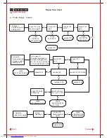
Page 40: ... 7121 pin 4 check 6161 Ok replace 7121 check 6111 3106 3111 7111 Ok NO OK No replace 5130 No check 7143 pin3 voltage dip check 7143 pin1 12V pin1 15V check 7121 pin 1 Ok check 6152 3151 3153 7151 2142 No check 5V loading current Turn power off check the resistance for all output voltages 210 80 15 15 6 3 5V check 6131 6133 6134 6137 6139 replace 5130 check 7141 7155 7144 7151 3 Sympton abnormal so...

Page 41: ... VG1 190V Ok No check blanking 7421 pin16 check heater 6 3V Ok check Xray prot 7651 pin14 No 2 Sympton no video or dim only raster with without retrace line green LED on check Vg1 Vg1 0V check cathode 80V 180V Ok check blanking 7421 pin16 No turn down Vg2 check 7705 pin 1 3 5 output swing check 7421 pin16 check VG2 350V Ok No check 7781 pin10 VFLB 3 Sympton no OSD or OSD out of sync check 7701 pin...

Page 42: ...ist check 2443 parabola exist 3 Sympton H linearity H DC full freq range replace 3523 check 7502 refer 7421 check list 5 Sympton H_dc shift check 7542 7543 check 7421 pin 32 enter OSD function disable morier check 7601collector check 7545 collector 7544 emitter 6 Sympton Focus check B Control 7422 7423 base check B Control 7541 base check B Control check B Control 7421 base refer cpu chece list ch...

Page 43: ...n one horizontal line V_size is abnormal too large small small check 7567 pin2 pin3 ramp exist check 15V 3569 6567 good replace 3578 3580 7567 No Ok replace 3569 6567 7567 Ok No check 7421 check 3571 3572 Ok No Repair Flow Chart 43 109P2 GS3 CM25 9 Go to cover page Forward Back ...

Page 44: ...in 2 sync out of rang Fhin 110KHz Fvin 160Hz check pin18 normal Hi blank low 6 7 P S LED check pin6 7 3 Blank check pin2 normal low change timing Hi Hor Freq KHz Q6 Q5 Q4 Q3 Q2 Q1 33 00 1 1 1 1 1 1 33 00 36 00 0 0 0 0 1 1 36 00 42 00 0 0 0 1 0 1 42 00 45 00 0 0 1 1 1 0 45 00 47 50 0 1 1 0 1 0 47 50 49 00 1 0 1 0 1 0 49 00 52 00 1 0 0 0 1 0 52 00 55 00 0 0 0 0 1 0 55 00 58 50 1 1 1 1 0 0 58 50 61 5...

Page 45: ...n38 hi scl pin39 hi 38 39 IIC bus check keys ok up down left right 33 Keypad check pwm from 0V to 5V 4 Rotation check pwm from 0V to 5V 30 Brightness check 3319 3891 3895 40 41 EEPROM write protection check pin40 pin41 write low low read don t care normal hi hi check 7336 M24C16 7421 TDA4856 7781 LSC4389 7701 TDA4886A check from 5V to 0V 26 Reset check 6302 3322 2317 6301 check active hi no active...

Page 46: ...or the square output waveform d pin6 pwm output to 7422 7423 base pin16 CLBL hi if no exist 3 4 5 6 B control 1 HFLB from H defl to H_deflection 7425 7426 base Vcc pin10 12V gnd pin7 pin25 0v Vertical blank will be activated hi 1 pin30 softstart pll2 0V 2 pin26 pll1 is unlock in searching mode 3 pin1 HFLB no exist 4 pin10 Vcc 9V 16 CLBL to B control east west control differential input to 7567 pin...

Page 47: ...HT_compen to 7503 pin30 for soft start compensate for the V_size owing the load variation 1 compare the HFLBand control the phase of HDRV 2 softstart compensate for the H_size owing the load variation 31 EHT_compen 32 Focus to 7603 for the V dynamic focus Hunlock pin is floating while pll1 pin26 is unlock in searching mode 17 Hunlock 18 IIC SCL hi 19 IIC SDA hi initial fail could be these of IC 74...

Page 48: ...TURE CONFIGURATIONS ARE ALWAYS MAINTAINED WHEN SWITCH BETWEEN COMMON VIDEO MODES AND USER DEFINED CUSTOM MODES USER FRIENDLY OSD DISPLAY FOR MODE IDENTIFICATION ADJUSTMENT DDC1 2B COMMUNICATION CAPABILITY MAX RESOLUTION 1920 X 1440 NON INTERLACED AT 60 HZ 19 0 24 MM AG MASK NF PICTURE TUBE EASY TILT SWIVEL BASE FULL RANGE POWER SUPPLY 90 264 VAC CE ENVIRONMENTAL POLICY with MHR Option FLAT SQUARE ...

Page 49: ...ure 2 10 Regulatory compliance 3 0 Electrical characteristics 3 1 Interface signals 3 2 Interface 3 2 1 Cable 3 2 2 Adaptor 3 2 3 OSD function control 3 3 Timing requirement 3 3 1 Mode storing capacity 3 3 2 Factory preset timings 3 3 3 Horizontal scanning 3 3 4 Vertical scanning 3 4 Power input connection 3 5 Video amplifiers 3 6 Degaussing 3 7 Requirement for low emission 3 8 Power management 3 ...

Page 50: ...ent 4 16 White uniformity 4 17 Color tracking on full white pattern 4 18 Purity 4 19 Moir 5 0 Mechanical characteristics 5 1 Controls 5 2 Unit dimension weight 5 3 Tilt and swivel base 5 4 Transportation packages 5 4 1 Shipping dimension weight 5 4 2 Block unit pelletization 6 0 Environmental characteristics 6 1 Susceptibility of display to external environment 6 2 Transportation tests 6 3 Display...

Page 51: ...S global styling cabinet which has an integrated tilt and swivel base 2 1 CRT Type NR M46LRY22X21 MITSUBISHI Dimensions 19 NF Phosphor Pitch 0 24 mm Phosphor B22 Mask AG Deflection angle 90 deg Light transmission 40 Surface of plate AR Film EHT 25 0 KV Useful screen mm 366 2 X 274 6 2 2 Scanning frequencies Hor 30 111KHz Ver 50 160 Hz 2 3 Video dot rate 261MHz 2 4 Power input 90 264 Vac 47 63 Hz 2...

Page 52: ... requirement regulation DHHS 21 CFR Subchapter J ROEV 08 01 1987 4 Low Radiation TCO99 5 Environmental Per CE and BU policy 6 Ergonomic Requirements ZH 1 618 EN 9241 3 ISO 9241 3 7 92 ISO 9241 8 3 0 Electrical characteristics 3 1 Interface signals The input signals can be applied in two different modes 1 Video Hsync Vsync 2 Video Composite Sync Video 0 7 Vp p input impedance 75 ohm Sync Separate s...

Page 53: ...ielded cable Length 1 5 m 50 mm detachable Connector type 15 pin D Sub male to 15 pin D Sub male blue IBM PS 2 standard 3 rows with DDC1 2B pin assignments pin assignments pin number 1 Red video input 2 Green video input Sync on green 3 Blue video input 4 Optional connected to pin 10 5 Not connected 6 Red video ground 7 Green video ground 8 Blue video ground 9 5V 10 Sync ground 11 Optional connect...

Page 54: ...UTO SCAN CMTR TYPE 109P20 00C CM25 109P2 BRAND PHILIPS 3 2 2 Adaptor 15 pin D standard 2 rows male to 15 pin D sub female for Apple MacIntosh II use Option pin assignments pin no 15 Pin D standard 1 RED GND 2 RED VIDEO 3 COMPOSITE SYNC 4 SYNC GND 5 GREEN VIDEO 6 GREEN GND 7 NC 8 NC 9 BLUE VIDEO 10 NC 11 NC 12 NC 13 BLUE GND 14 NC 15 NC ...

Page 55: ...ain Controls Language Zoom Adjust horizontal Adjust vertical Adjust shape Adjust color Reset to factory settings Extra Controls Close Main Controls Move selection then Language Language multi language at least 5 language Input Input signal selection Zoom Zoom Adjust horizontal Adjust position Adjust size Adjust vertical Adjust position Adjust size Adjust shape Adjust side curve Pincushion Balanced...

Page 56: ...ch User preset Reset to factory settings No Yes Extra Adjust moire Horizontal degauss Adjust convergence Horizontal Vertical Adjust purity Top left Top right Bottom left Bottom right Auto calibrate 3 3 Timing requirement 3 3 1 Mode storing capacity Total modes available 52 1 Factory modes 36 Including 7 preset mode 2 User modes 16 3 3 2 Factory preset timings The factory settings of size and cente...

Page 57: ...Hz 75 000 Hz O ms 14 268 16 683 14 268 13 333 P ms 0 064 0 064 0 064 0 080 Q ms 1 907 1 049 1 112 0 427 R ms 11 122 15 253 12 711 12 800 S ms 1 175 0 317 0 382 0 026 SYNC H V POLARITY SEP SYNC Y Y Y Y MODE NO 5 6 7 8 RESOLUTION 640 x 480 640x350 800x600 720x400 Dot clock MHz 31 500 31 500 40 000 35 500 f h 37 861 kHz 37 861 kHz 37 879 kHz 37 927 kHz A us 26 413 26 413 26 400 26 366 B us 1 270 2 03...

Page 58: ...0 004 Hz O ms 11 763 13 333 13 853 16 666 P ms 0 069 0 064 0 125 0 124 Q ms 0 578 0 448 0 478 0 600 R ms 11 093 12 800 12 480 15 880 S ms 0 023 0 021 0 77 0 062 SYNC H V POLARITY SEP SYNC Y Y Y Y MODE NO 13 14 15 16 RESOLUTION 832 x 624 640 x 480 800 x 600 1024 x 768 Dot clock MHz 57 280 40 500 56 250 75 000 f h 49 722 kHz 50 628 kHz 53 674 kHz 56 476 kHz A us 20 110 19 752 18 631 17 707 B us 1 11...

Page 59: ...60 020 Hz O ms 16 667 13 328 9 997 16 661 P ms 0 050 0 050 0 047 0 047 Q ms 0 600 0 466 0 548 0 594 R ms 16 000 12 795 9 387 16 005 S ms 0 017 0 017 0 015 0 015 SYNC H V POLARITY SEP SYNC Y Y Y Y MODE NO 21 22 23 24 RESOLUTION 1152 x 864 1024 x 768 1152 x 870 1152 x 900 Dot clock MHz 108 000 94 500 100 000 108 000 f h 67 500 kHz 68 677 kHz 68 681 kHz 71 809 kHz A us 14 815 14 561 14 560 13 926 B u...

Page 60: ... 999 Hz O ms 16 667 13 329 15 385 16 667 P ms 0 040 0 038 0 037 0 036 Q ms 0 613 0 475 0 566 0 550 R ms 16 000 12 804 14 769 16 069 S ms 0 014 0 012 0 013 0 012 SYNC H V POLARITY SEP SYNC Y Y Y Y MODE NO 29 30 31 32 RESOLUTION 1280 x 960 1856 x 1392 1600 x 1200 1920 x 1440 Dot clock MHz 148 500 218 250 189 000 234 000 f h 85 938 kHz 86 333 kHz 87 500 kHz 90 000 kHz A us 11 636 11 583 11 429 11 111...

Page 61: ...4 Hz 75 000 Hz 85 000 Hz 74 997 Hz O ms 11 761 13 334 11 765 13 334 P ms 0 033 0 032 0 028 0 028 Q ms 0 483 0 491 0 433 0 649 R ms 11 234 12 800 11 294 12 647 S ms 0 011 0 011 0 01 0 01 SYNC H V POLARITY SEP SYNC Y Y Y Y 3 3 3 Horizontal scanning Sync polarity Positive or Negative Scanning frequency 30 111 KHz Retrace time 1 8 µsec typical 3 3 4 Vertical scanning Sync polarity Positive or Negative...

Page 62: ...n 1 Electro static potential 0 5 KV 2 Alternating Elec field ELF 5 2 Khz 10 0 V M VLF 2 400 KHz 1 0 V M 3 Magnetic field ELF 5 2 Khz 200 nT VLF 2 400 Khz 25 nT 3 8 Power management The power consumption and the status indication of the set with power management function are as follows On Pulse Pulse as normal on Green Stand by No Pulse Pulse 10 W Yellow Suspend Pulse No Pulse 10 W Yellow Power off...

Page 63: ...put impedance with 0 7Vpp video level 2 Luminance setting controls to be set to 20 ft lb with full screen 100 duty cycle white signal 3 Warm up more than 30 minutes after power on with signal supplied 4 Ambient light 400 600 lux 5 Ambient temperature 20 5 c 6 Ambient magnetic field no special ambient magnetic field existed the ac leakage flux dc flux caused by transformer magnet etc 7 CRT face Eas...

Page 64: ...of horizontal and vertical axis of the screen are listed below see Fig 1 355 4 mm X 265 4 mm 4 5 2 Max scan size Maximum active video size should be not smaller than mask opening The mask opening is 366 2 x 274 6 mm 4 6 Image centering deviation A B and C D 6 mm please see Fig 2 4 7 Picture shift range H shift range total 30 mm V shift range total 15 mm 4 8 Display dimension stability Due to brigh...

Page 65: ...hould be measured on a white line and represents the maximum distance between the center of the red green and blue lines over the whole image area Max misconvergence 0 15 mm in C zone Picture area 355X265 See Fig 6 0 30 mm in A zone 0 40 mm in B zone 4 13 Focus check First adjust brightness to 50 position and contrast to max and then generate characters for 1024 lines to cover entire picture area ...

Page 66: ...nter of the screen being in the range of 20 22 ft lb The color coordinate at any point on the screen should be X X center 0 015 Y Y center 0 015 4 17 Color tracking on full white pattern Adjust the contrast control from max to min with brightness at click position The color coordinates should not deviate more than x x center 0 015 y y center 0 015 4 18 Purity Conditions With full color pattern wit...

Page 67: ...el base The display should be equipped with a tilt swivel device allowing rotation over an angle of 90 degree left or rightward and for a tilt of 5 degree to 15 degree with respect to the horizontal position 5 4 Transportation packages 5 4 1 Shipping dimension Weight Carton dimension 557 W x 627 H x 596 D mm Gross weight 28 0 Ó 0 5Kg 5 4 2 Block unit Palletization layers block sets layer sets bloc...

Page 68: ...ed 6 2 Transportation tests European version USA version Standard Philips UAN D1400 NSTA Height 50cm 45cm 1 corner 1 corner Drop Sequence 3 faces 3 edge Test 6 face electrical function ok Test mechanical function ok Result no serious damage on set appearance room temp 10 c humidity 70 7 HZ 5 100 5 Hz Sequence 1 05 G 0 5 G 30 min for 15 min for Vibration each axis each axis Test Test electrical fun...

Page 69: ...rotection ICRP requirement 0 5 mR hrs 7 0 Reliability 7 1 Mean Time Between Failures MTBF to be calculated according to military standard MIL HDBK 217C MTBF 75 000 hrs excluding CRT Total hrs power on x Total sets Practice of MTBF NO of failed sets 8 0 Quality assurance requirements 8 1 Acceptance test according to MIL STD 105D Control II level AQL 0 65 major 2 50 minor please also refer to annual...

Page 70: ...DUCT SPECIFICATION 9 Go to cover page Forward Back 8639 000 10535 00 08 01 JACK LIN 00 08 01 590 23 31 19 AUTO SCAN CMTR TYPE 109P20 00C CM25 109P2 BRAND PHILIPS 351 359 355 261 265 269 FIG 1 IMAGE DIMENSION m m m m m m m m m m m m ...

Page 71: ... PRODUCT SPECIFICATION 9 Go to cover page Forward Back 8639 000 10535 00 08 01 JACK LIN 00 08 01 590 24 31 19 AUTO SCAN CMTR TYPE 109P20 00C CM25 109P2 BRAND PHILIPS FIG 2 IMAGE CENTERING 355 265 A B AND C D 6 mm mm mm C D A B ...

Page 72: ... GENERAL PRODUCT SPECIFICATION 9 Go to cover page Forward Back 8639 000 10535 00 08 01 JACK LIN 00 08 01 590 25 31 19 AUTO SCAN CMTR TYPE 109P20 00C CM25 109P2 BRAND PHILIPS FIG 3 IMAGE ROTATION 265 1 1 355 mm mm mm mm ...

Page 73: ...ENERAL PRODUCT SPECIFICATION 9 Go to cover page Forward Back 8639 000 10535 00 08 01 JACK LIN 00 08 01 590 26 31 19 AUTO SCAN CMTR TYPE 109P20 00C CM25 109P2 BRAND PHILIPS FIG 4 IMAGE GEOMETRY 355 265 mm mm B A A B 2 5 mm ...

Page 74: ...FICATION 9 Go to cover page Forward Back 8639 000 10535 00 08 01 JACK LIN 00 08 01 590 27 31 19 AUTO SCAN CMTR TYPE 109P20 00C CM25 109P2 BRAND PHILIPS 100 265 355 100 FIG 5 BRIGHTNESS AND CONTRAST mm mm mm MEASUREMENT AREA ZONE B ZONE A mm ...

Page 75: ...RAL PRODUCT SPECIFICATION 9 Go to cover page Forward Back 8639 000 10535 00 08 01 JACK LIN 00 08 01 590 28 31 19 AUTO SCAN CMTR TYPE 109P20 00C CM25 109P2 BRAND PHILIPS FIG 6 MISCONVERGENCE 355 265 mm mm ZONE C ZONE A ZONE B ...

Page 76: ...00 10535 00 08 01 JACK LIN 00 08 01 590 29 31 19 AUTO SCAN CMTR TYPE 109P20 00C CM25 109P2 BRAND PHILIPS Fig 7 CHARACTER FORMAT FOR FOCUS CHECK 7 6 5 4 3 2 1 0 LINE HEX DATA 0 0 0 0 0 0 0 0 0 0 0 0 0 0 0 0 0 0 1 2 2 E 2 2 0 C C C 2 3 3 3 4 4 4 4 5 5 5 5 5 6 7 8 9 A B C D E F 1 BYTE 8BITS ...

Page 77: ...er page Forward Back 8639 000 10535 00 08 01 JACK LIN 00 08 01 590 30 31 19 AUTO SCAN CMTR TYPE 109P20 00C CM25 109P2 BRAND PHILIPS D VIDEO C E SEPARATE SYNC HORIZONTAL B A R VIDEO Q S P O D VIDEO C E B A VERTICAL HORIZONTAL COMPOSITE SYNC FIG 8 TIMING CHART 1 ...

Page 78: ... GENERAL PRODUCT SPECIFICATION 9 Go to cover page Forward Back 8639 000 10535 00 08 01 JACK LIN 00 08 01 590 31 31 19 AUTO SCAN CMTR TYPE 109P20 00C CM25 109P2 BRAND PHILIPS VIDEO VERTICAL FIG 9 TIMING CHART 2 O P Q R S ...

Page 79: ... for this prudent routine is cleary understood by everyone It is important to use an accurate and reliable HV meter It is recommended that the HV recorded on each customer s invoice which will demonstrate a proper concern for the customer s safety 5 When troubleshooting and making test measurements in a receiver with a problem of excessive high voltage reduce the line voltage by means of a Variac ...

Reviews: