


9
109P2 GS3 CM25
DDC Instructions
Additional information :
There are two chips (IC) to store the serial number of monitor
as below.
DDC IC (with EDID data)
OSD IC (EEPROM)
To write the serial number of monitor to DDC IC and OSD IC
simultaneously.
Please follow the indications as below.
- Access the factory mode of monitor.
- Execute DDCV2A F0.EXE
- Follow DDC instructions to write serial number to DDC IC and OSD
IC.
- Turn off monitor (leave factory mode).
- Press OSD button, select MONITOR STATUS, verify the updated
serial number of monitor.
DDC Instructions
Additional information about DDC (Display Data Channel)
may be obtained from Video Electronics Standards
Association (VESA).
Extended Display Identification (EDID) information may be
also be obtained from VESA.
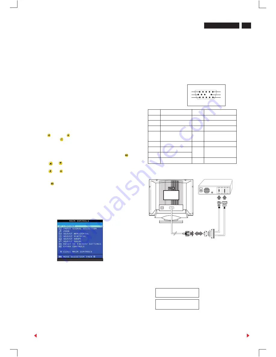
Pin assignment
The 15-pin D-sub connector (male) of the signal cable (3 rows)
for DDC feature :
Pin No. Assignment
Pin No. Assignment
1
Red video input
9
No pin
2
Green video input
10
Logic ground
3
Blue video input
11
Connected to pin 10
4
Connected to pin 10
12
Serial data line
(SDA)
5
Ground
13
H.sync/H+V
6
Red video ground
14
V. sync (VCLK for
7
Green video ground
DDC)
8
Blue video ground
15
Data clock line(SCL)
5
10
15
1
6
11
This [DDC Module (DDC cable)= 4822 320 12004(=4822 724 27550)]
and
[DDC V2(DDCV2A .EXE) software(3.5" disk)=3138 106 10065 ]
are used for "BU Monitor - Chungli product range" which
incorporates a DDC1/DDC2B function that allows
bi-directional communication between the monitor and
PC system for optimal video configuration.
[January 31 2000, Revision 3.3] ,which upgrades the software and
service information(4822 727 21027 & 4822 727 21038) , is fully
compatible with previous one (DDCV2A F0.E
XE).
1. General
In case the DDC data memory IC, replaced due to a defect the
data contents of this IC have to be re- programmed via a PC.
In case of replacement of the video (or deflection) board it is
advised to re-soldered DDC IC from the old board onto the new
board, in this case the IC dose not need to be re-programmed.
2. DDCV2A.EXE can be used for :
EDID Structure Version/Revision
Version
: 1
Revision
: 0
(text file)
and
Version
: 1
Revision
: 2
(.hex file)
DDC data re-programming
(Rear of the monitor)
Connection
Video cable
To
video
card
To
printer
port
(L
TP1)
To access factory mode:
-
Turn off monitor (don't turn off PC)
- Hold "
" and "
" simultaneously on the front control panel,
then press "
", wait till the OSD menu with characters "
factory mode (below OSD menu)" come on the screen of monitor
as shown in Fig. 1 .
- If OSD menu disappears on the screen of monitor, press "
"
again (anytime), then the OSD menu comes on the screen again.
- using "
,
" : to select OSD menu.
"
" : to increase or decrease the setting.
- Using "
" to confirm the selection.
* After alignment of factory mode, turn off monitor (if you do not turn
off monitor, the OSD menu is always at the factory mode), then turn
on monitor again (at this moment, the OSD menu goes back to
user mode).
To leave factory mode
,
Fig 1
00195
109P V3.08 000601
9
Go to cover page
Forward
Back


