background image

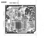
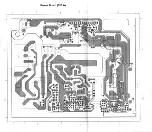
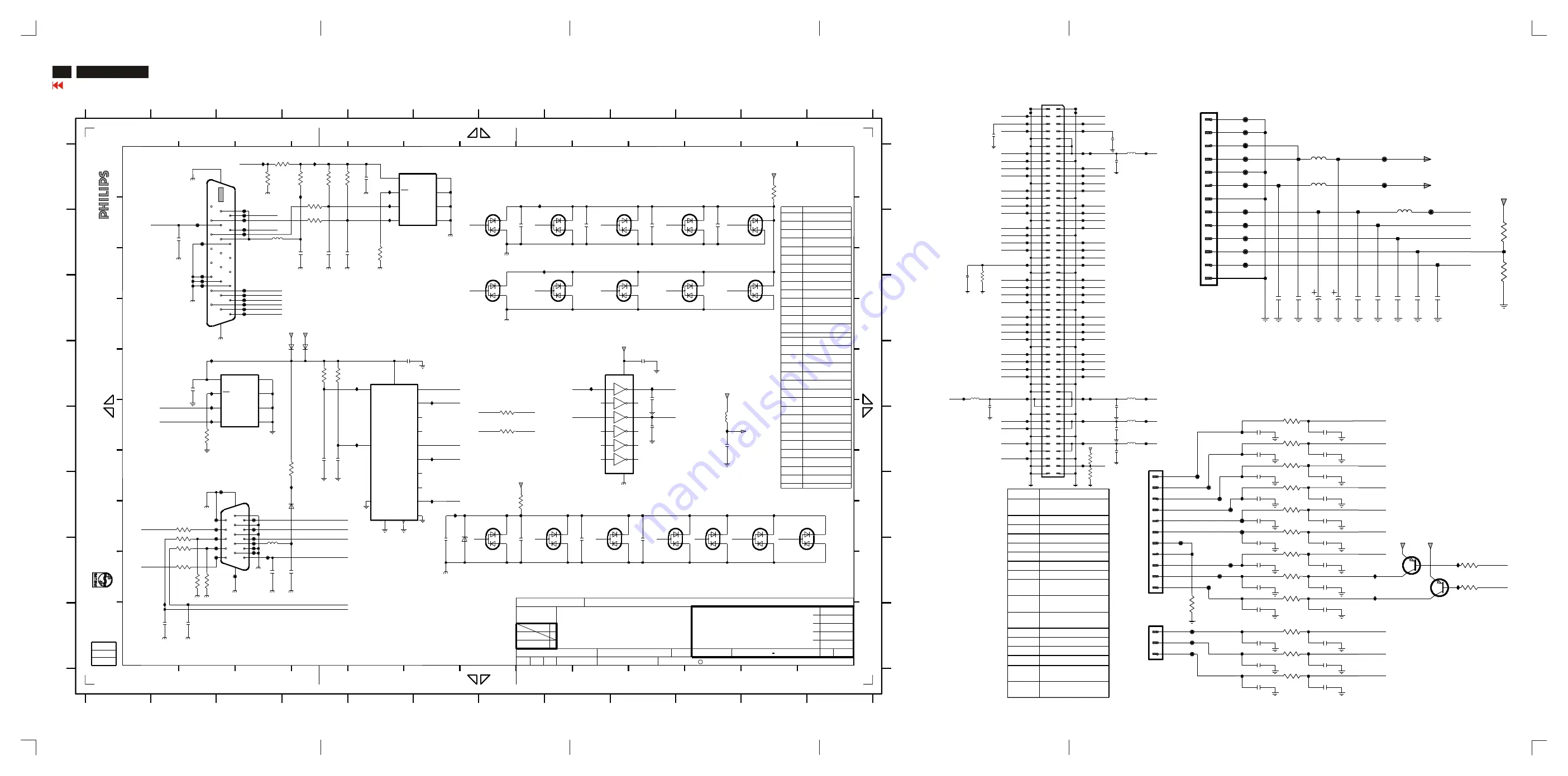
Schematic Diagram (Input DVI & D- SUB)

48

150B3B LCD

Connector Diagram

Go to cover page

C

933215370215

BAV99

6212

933215370215

BAV99

319801731040

100n

2205

319801731040

100n

2206

319801731040

100n

2207

319801731040

10K

BAV99

6217

933215370215

232270296001

0R

2

13

6203

933215370215

BAV99

6204

933215370215

BAV99

6205

933215370215

BAV99

6206

6213

933215370215

BAV99

6210

933215370215

SCALER BOARD

SB: 55541 x4

PB: 55551

EXCEPT 1201,1203 WERE CHIP COMPONENTS.

2202

319801731040

100n

2203

BAV99

BAV99

6209

BAV99

6211

B

A

100n

2208

6214

933215370215

BAV99

6215

933215370215

BAV99

6216

33p

3211

933215370215

I026 H2
I028 E10
I151 F4
I154 B7

3233

232270296001

0R

3234

All

 rights

 reser

v

ed

. R

e

production

 in

 whole

 or

 in

 parts

I

H

G

F

4

3

12

11

933215370215

BAV99

6207

933215370215

BAV99

6208

933215370215

933215370215

F110 F3
F111 F2
F112 F2
F113 G2

gedeeltelijk

, is

 niet

 toegestaan

 dan

 met

 schriftelijk

e

Alle

 rechten

 voorbehouden

. V

e

rv

eelvuldiging

, geheel

of

8

7

F118 F3
F119 G3
F120 G3

F121 G3
F122 G3

319801731040

100n

2204

D

C

I009 B5
I010 A4
I011 A7
I012 D2
I013 D2
I014 E2
I015 E2
I017 F6
I018 G4
I019 D6
I020 D5
I021 E6
I022 E5
I023 F6

6222 D4
7202 D3
7203 A6

9

I155 D8
I157 D9
I158 E9

J

5

11

10

1

J

10

9

8

F096 C3
F097 C3
F098 C3
F099 C3
F100 A3
F101 B3
F102 B3
F103 B3
F104 B3
F105 B2
F106 B2
F107 C2
F108 C2
F109 C2

3230 E2
3231 E4
3232 F7

F114 G3
F115 G3
F116 G3
F117 F3

3234 E7
5201 B3
5202 G3
5203 E10
6202 G6

F127 G3
I005 A3
I006 A4
I007 A5
I008 A5

6208 G11
6209 G11
6210 B7
6211 B8
6212 B9
6213 B10
6214 B11
6215 C7
6216 C8
6217 C9
6218 C10
6219 C11
6220 D4
6221 F4

3206 B4
3207 A4
3208 A4

D

6

2

3

4

1

7

6

5

owner

.

I

7206 F8
7208 E5
F094 C3
F095 C3

A

B

C

3209 A3
3210 A3
3211 A11
3221 D4
3222 D4
3223 F2
3224 G2
3225 G2
3226 F2
3227 G2
3228 G2

2217 E4
2218 H2
2219 H2

100n

3233 E7

319801633390

232270281102

1K

6203 G7
6204 G8
6205 G8
6206 G9
6207 G10

Ref Des NI_1

2201

319801731040

2220 G3
2221 G4
2222 D5
2225 E10
2226 D9
2231 D9
2232 E9
3202 A4
3203 A4
3204 B5

7

8

9

319801731040

toestemming

 van

 de

 auteursrechthebbende

.

is

 prohibited

 without

 the

 written

 consent

 of

 the

 copyright

E

2207 B9
2208 B10
2209 A5
2210 B4
2211 B4
2212 B4
2214 B2
2215 D2
2216 E4

2204 G9
2205 B7
2206 B8

933137390215

2231

319801731030

10n

2232

933215370215

6219

BAV99

933215370215

6218

3232

319802131030

100n

E

5

6

7

8

9

10

11

12

1

2

3

4

5

6

H

G

F

12

13

10

11

12

A

B

C

D

E

F

G

H

A

B

C

D

E

F

G

H

1201 A2
1203 F3
2201 G6
2202 G7
2203 G8

6202

933913910115

6220

BAV99

BAV99

1

2

3

4

100n

2226

GND

14
VCC

1

3

5

9

11

13

2

4

6

8

10

12

+3.3V

F109

TGND

74LVC14APW-T

7206

7

3206

100R

100R

3207

10K

6213

BAV99

F107

3210

I019

I020

TGND

F113

2206

100n

F120

F127

A3

DSUB/DVI

150S3F/00C

3138 158 54421

CHECK

MGr

DATE

NAME

SUPERS.

CLASS_NO

CHN

SETNAME

100n

YT Liu/Joss Hung

HUDSON 150S/150B

5

1

********

02-01-18

KONINKLIJKE PHILIPS ELECTRONICS N.V. 2000

CT

--------

TYT12-

02-01-18

3

***

10

***

E0

1

E1

2

E2

3

SCL

6

SDA

5

VCC

8

VSS

4

WC

7

2204

BA

S32L

6221

7202

M24C02-MN6T

F098

F096

F097

F094

F095

2219

220p

I010

3203

10K

I011

I015

F104

Y2

4

Y3

13

Zx

3

Zy

I028

10

A

9

B

6

INH

16

VDD

7

VEE

8

VSS

12

X0

14

X1

15

X2

11

X3

Y0

1

5

Y1

2

2207

100n

74HC4052D-T

7208

19

2

20

21

22

23

24

3

4

5

6

7

8

9

25

26

1

10

11

12

13

14

15

16

17

18

2210

100n

74320-4004

1201

3202

10K

TGND

5K6

3228

F101

+5V

I017

I005

I006

BAV99

6204

CGND

6205

BAV99

100n

2209

TGND

6217

BAV99

5202

6209

BAV99

5K6

3227

3211

1K

330p

2216

TGND

CGND

I013

I012

I009

100R

3231

6220

2215

BA

T42W

6222

6219

BAV99

100n

330p

2212

6212

6202

100n

2201

BAV99

BAV99

6203

I007

I008

BAV99

6208

10R

3208

I018

5203

CGND

F115

F116

100R

F110

6215

BAV99

3226

+3.3V

BAV99

6216

11

12

13

14

15

2

3

4

5

6

7

8

9

1285-15S

1203

16

17

1

10

TGND

I026

3223

100R

BAV99

6218

2218

33p

F100

2205

100n

F106

100n

2214

F108

0R

3233

5201

BAV99

3225

100R

6206

100R

+3.3V

3234

0R

F099

3224

3232

F102

I022

10K

2202

100n

2203

100n

2222

100n

3209

TGND

6214

BAV99

10K

BAV99

6210

6211

BAV99

E0

1

E1

2

E2

3

6

SCL

5

SDA

VCC

8

4

VSS

WC

7

I021

M24C02-MN6T

7203

I154

F111

F114

I157

I158

6207

I155

0R

I151

BAV99

100n

3.3VD

3230

2221

2232

33p

100n

2208

F105

TGND

F118

TGND

TGND

F103

TGND

100n

2220

330p

2211

CGND

TGND

F119

2225

100n

3204

0R

F121

+12V

F117

2217 330p

F122

3222 10K

TGND

10K

3221

2231

10n

F112

I014

I023

UART_SEL

DDCSCL

VGASDA

VGASCL

DDCSDA

DDCSCL

3V3_6713

HS6713

HS

VS6713

VS

HS

DDCSDA

DDCSDA_D

DDCSCL_D

RIN

BIN

UART_TX

DDCSCL

VGASDA

UART_RX

VGASCL

VGASCL

VGASDA

+5_DVI

DDCSDA

RXC-

RX2-

RX1-

RX2+

RX0-

SDA

HIN

VIN

SCL

GIN

DSUB_CABLE

VS

VIN

HIN

SCL

SDA

BIN

RIN

GIN

RXC+

RX0+

RX1+

RX2+

RXC-

RX0-

RX1-

RX2-

DDCSCL_D

DDCSDA_D

RX1+

DVI_CABLE

RX0+

RXC+

3513

319802133310

3512

100R

319802131010

3511

33p

223886715339

1504

313816876361

JFE6338V

2506

319801731040

2534

223858615623

2535

223858615623

2540

223886715339

33p

2539

223858615623

2536

223858615623

2537

223858615623

313816874261

5507

2541

Ref Des NI_1

10K

2538

223858615623

319802133310

3514

319802133310

3515

319802131030

3518

319802131030

VCOM

2541

33p

99

84

85

86

87

88

89

9

90

91

92

93

94

95

96

97

98

7

70

71

72

73

74

75

76

77

78

79

8

80

81

82

83

56

57

58

59

6

60

61

62

63

64

65

66

67

68

69

40

41

42

43

44

45

46

47

48

49

5

50

51

52

53

54

55

26

27

28

29

3

30

31

32

33

34

35

36

37

38

39

4

12

13

14

15

16

17

18

19

2

20

21

22

23

24

25

1501

1

10

100

11

F048

F047

F049

F045

F126

33p

2540

F016

F015

F014

F012

F046

F131

F052

F051

F050

F053

5504

F011

F013

F009

F010

F019

F017

F020

F018

F059

F058

F057

F054

F056

F055

2502

100n

2503

100n

100R

5503

2533

3511

5502

10p

F124

F132

F125

F069

F065

F062

F061

F063

100n

F026

5501

2505

F024

F025

F023

F022

F021

5505

2504

100n

F044

F042

F040

F043

F036

F034

F033

F032

F030

100n

2501

F004

F003

F002

VDDD

F001

F008

F007

F005

F123

F006

F066

F068

F064

F067

3515

F027

F028

F060

F031

3516

10K

F029

F038

F041

F037

F039

F035

ERS5

LP

ERS6

ERS7

EGS4

EGS5

EGS6

EGS7

EBS4

EBS5

HMS2_E

EBS6

EBS7

REV

PANEL_ID

HMS1_O

OBS2

STV1

CLKH

ERS1

ERS0

ERS2

EGS1

EGS0

ERS3

EGS3

EBS0

EGS2

EBS3

EBS2

EBS1

ORS3

ORS4

ORS5

ORS6

ORS7

OGS4

OGS5

OGS6

OGS7

OBS4

OBS5

OBS6

OBS7

ERS4

VDDD

VDDG

VEEG

VDDA

GOE

CLKV

STH

STV2

POL

ORS2

ORS1

ORS0

OGS2

OGS1

OGS0

OBS1

OBS0

OGS3

OBS3

TO

 POWER

 BD

 8052

1K

10K

3518

3517

F079

F078

F077

2512

100n

F072

+5V

+3.3V

11

12

13

2

3

4

5

6

7

8

9

1502

JFE6339V

1

10

F076

F074

100n

2514

F129

F073

F130

+3.3V

5508

5506

F075

10u

10u

100n

2513

5507

F070

470u

2508

2507

100n

2506

F080

470u

2509

F071

2510

100n

100n

2511

F128

PANEL_ID

BRIGHTNESS

BL_CTL

+12_PWR

+12V

TO

 CONTROL

 BD

 1712

BC858C

7501

+3.3V

+3.3V

7502

BC858C

3501

2516

100R

F093

1n

3520

10K

10K

3519

1n

2523

2519

1n

2525

1n

3508

220R

F084

F087

F083

3514

2521

1n

220R

3509

I202

I204

I205

I203

2538

F082

2520

1n

2518

1n

F085

2515

1n

F090

100R

100R

3506

3503

100R

3504

1n

2532

1n

2530

F091

2526

1n

1n

3502

100R

2529

3512

2531

1n

2535

1n

2527

F092

100R

3505

3510

0R05

2522

1n

3507

100R

2524

1n

2528

1n

1

2

3

2539

JFE6338V

1504

1

10

11

2

3

4

5

6

7

8

9

1503

JFE6339V

F088

F089

F086

3513

F081

2536

2534

2537

2517

1n

LED_R

LED_G

K_AUTO

K_OK

K_DOWN

K_RIGHT

K_PWR

K_LEFT

K_UP

AUDIO_DET

AUDIO_PWR

VOLUME

Summary of Contents for 150B3B

Page 1: ... Management 3 4 Connection To PC 5 Installation Accessories 6 Description Of Controls 7 Advanced Control Of OSD 8 Clock Phase Adjustments 9 OSD Menu Control Level Structure 10 11 OSD Attention Signal 12 Trouble shooting 13 Failure Mode Of LCD Panel 14 Flat Panel Adjust FP Adjust 15 Definition Of Pixel Defects 16 Wiring Diagram 17 Mechanical Instructions 18 20 Electrical Instructions 21 Factory Adj...

Page 2: ...lease adjust the video mode to 1024x768 at 60Hz for best display quality The monitor will detect various display situation automatically When the monitor detects the problems the screen will show the different warning signals to remind you what is happen to your monitor WAIT FOR AUTOMATIC ADJUSTMENT This screen appears when you touch the button It will disappear when the monitor is properly adjust...

Page 3: ...sing the First Window The backlight of the LCD monitor has a fixed life span When the screen becomes dark or begins to flicker please contact your dealer If an image remains in the screen for an extended period of time it may be imprinted in the screen and leave an after image This usually disappears after a few hours This is characteristic of liquid crystal and is not caused by a malfunction or d...

Page 4: ...enomenon Vertical dim lines Vertical block defect Vertical lines defect Always bright or dark Horizontal block defect Horizontal dim lines Horizontal lines defect Always bright or dark Has bright or dark pixel Bright pixel Dark pixel Polarizer has bubbles Polarizer has bubbles Foreign material inside polarizer It shows linear or dot shape Concentric circle formed Bottom back light of LCD is bright...

Page 5: ...In MS Windows 95 98 environment For example 1 Insert CD DFU 3138 117 03111 to your CD ROM driver 2 Run F PC FPADJUST FP_SETUP01 EXE as Fig 1 3 Then follow the instructions to install the FPadjust program When finish double click FPadjust icon then the description can be moved by mouse and background pattern come on the screen for image adjustment FPadjust program is working as a pattern generator ...

Page 6: ...ls that are always dark or Off These are the types of black dot defects One dark subpixel Two or three adjacent dark subpixels 3 Pixel Defect Tolerances In order to qualify for repair or replacement due to pixel defects during the warranty period a TFTLCD panel in a PHILIPS flat panel monitor must have pixel or subpixel defects exceeding the tolerances listed in the following tables Pixel Subpixel...

Page 7: ...2 15 Hudson2 15 8639 000 11737 8639 000 11737 2002 01 14 2002 01 14 JACKSON LAI JACKSON LAI 1 10 132 1 TY 2002 01 14 2002 01 14 C PHILIPS ELECTRONICS INDUSTRIES TAIWAN LTD BE C PHILIPS ELECTRONICS INDUSTRIES TAIWAN LTD BE 8052 8052 8051 8051 1501 1501 CTRL P C B CTRL P C B PANEL CONNECTOR PANEL CONNECTOR D SUB D SUB AC IN AC IN DVI D DVI D SCALER P C B SCALER P C B POWER P C B POWER P C B DC 12V O...

Page 8: ...bezel Push the button located underneath the monitor and slide the bezel up at the same time Repeat step for the other side 2 Pull forward to remove the front bezel from the monitor 3 Peel off the film from both sides of the protective cover 4 Mount the protective cover by first aligning its clip onto the guide line on above of the control panel A then press on B 5 Push down the protective cover t...

Page 9: ... Bezel from down to up see Fig 1 2 Control panel removal Fig 2 Step1 Remove the 7pins connectors 1712 Step2 Release two screws 3 Back cover removal Step1 Release four screws see Fig 3 Step2 Pull out LG frame panel then rotate LG frame to find out Scaler board power board and interver board Fig 4 Fig 3 Fig 4 Polarizer upper 9965 000 12835 Polarizer lower 9965 000 12836 CCFT upper 9965 000 12837 CCF...

Page 10: ...e Mechanical instructions Fig 7 Source PCB Cover Stick Gate PCB Cover Stick Tab IC Source driver 9965 000 12833 Source driver PCB Assy 9965 000 12839 Tab IC Gate driver 9965 000 12834 Gate driver PCB Assy 9965 000 12832 Fig 8 Fig 9 ...

Page 11: ...1 7 The white balance color temperature has to be tested in subdued lighted room 1 8 Repetitive power on off cycle are allowed except it should be avoided within 6 sec 2 Input signal 2 1 Signal type Video 0 7 Vp p linear positive polarity Sync TTL level separate positive or negative polarity Signal source pattern generator format as attachment table 1 to 14 Reference generator CHROMA 2200 or 2250 ...

Page 12: ...ncrease the value of each item adjust Sub brightness Sub contrast automatically AUTO Factory Mode Adjustment Entering Factory Adjustment Menu Push buttons then power on the monitor release them after picture display normally Press button to bring up OSD menu of factory mode as shown below Use button to select factory adjustment indication for example HUDSON 150P V1 56D 01 03 09which is the entranc...

Page 13: ...nt voltage 2000VAC 1200VAC 25A AC Test time Test time 3 seconds 1 second 3 seconds min min Resistance required Trip set at 100 uA 5 mA 0 09 R ohm current for Max R is the Tester limitation set resistance of at 0 1 uA for the mains cord Min limitation Ramp set at 2 time seconds Tester 23 150B3B LCD Go to cover page Safety Test Requirements 2 2 1 The test with AC voltage is only for production purpo...

Page 14: ... about DDC Display Data Channel may be obtained from Video Electronics Standards Association VESA Extended Display Identification Data EDID information may be also obtained from VESA DDC EDID structure For Analog interface Standard Version 3 0 Structure Version 1 2 For Digital inferface Standard Version 3 0 Structure Version 1 3 System and equipment requirements 1 An i486 or above personal compute...

Page 15: ...2 Connecting printer cable and video cable of monitor as Fig A Step 3 Run the EDID301 EXE program until the main menu appears This is for initialize alignment box Re programming DDC IC Step 1 After initialize alignment box connecting all cables and box as Fig 3 Step 2 Press and hold and buttons then power on the monitor Step 3 Follow the steps on DDC re programming instructions to staring re progr...

Page 16: ...N at Product information of the OSD menu after restarting the monitor 4 Click button The main menu appears as shown on Fig 6 Note If the connection is improper you will see the following error message before entering the main menu Meanwhile the read EDID function will be disable At this time please make sure all cables are connected correctly and fixedly and the DDC Instructions 6 Click icon to re...

Page 17: ...irmed that model and serial number are correct and match with the monitor you are trying to re write TY00 0105000001 Modify DDC data Serial No 1 Click icon on the toosl bar 2 Click till the Step 7 of 9 window appears 3 Type the new Serial No for example TY00 0105000001 4 Click till the last step window appears then click to exit the Step window Note During the loading EDID30 will verify the EDID d...

Page 18: ...m 1 Click file command on the command bar then select Exit Definition of Serial Number T Y 0 0 0 1 0 5 0 0 0 0 0 1 Serial Number U S A 8 digit Week Year TY Code TY Chungli CX Dong Guan HD Hungary BZ Suzhou YA Mexico IO Raleigh Other regions 6 digit ...

Page 19: ...nused Detailed Timing 1 Pixel Clock MHz 65 H Active pixels 1024 H Blanking pixels 320 V Active lines 768 V Blanking lines 38 H Sync Offset F Porch pixels 24 H Sync Pulse Width pixels 136 V Sync Offset F Porch lines 3 V Sync Pulse Width lines 6 H Image Size mm 307 V Image Size mm 230 H Border pixels 0 V Border lines 0 Flags Non interlaced Normal Display No stereo Digital Separate sync Negative Vert...

Page 20: ...nused Detailed Timing 1 Pixel Clock MHz 65 H Active pixels 1024 H Blanking pixels 320 V Active lines 768 V Blanking lines 38 H Sync Offset F Porch pixels 24 H Sync Pulse Width pixels 136 V Sync Offset F Porch lines 3 V Sync Pulse Width lines 6 H Image Size mm 307 V Image Size mm 230 H Border pixels 0 V Border lines 0 Flags Non interlaced Normal Display No stereo Digital Separate sync Negative Vert...

Page 21: ...tton 1 button 2 button 3 When the serial number inside DDC IC has been changed the Serial number modification in EEPROM near CPU for On Screen Display Factory mode User mode serial number inside EEPROM in User mode the serial number of monitor can be found by OSD as shown in Fig 1 also should be changed at the same time RS232 I2C I2C I2C Due to different communication structures were implement for...

Page 22: ...C CFG DDC HEX DDCRUN EXE as shown in Fig 8 C IICRS232 RS232EXE DDCRUN press Enter Bring up definition of Barcode format setting as shown in Fig 11 C IICRS232 RS232EXE DDCRUN PHLW_RD T YxxYWWSSSSSS press Enter Bring up contents of DDCRUN as shown in Fig 12 Press Enter Bring up Fig 14 to ask Entry Factory mode Press Enter Bring up Fig 15 new series number write down success Press Enter Bring up Fig ...

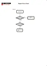
Page 23: ...ard Main panel 620Vrms Inverter panel Fluorescent Lamp LCD panel Audio control Unit 3 3VDC Optional 12V DC 12V DC Speaker No power power indicator off Check 12V 3 3V DC No Yes Bad AC adapter Power supply board Replace Main panel Go to cover page Audio in Control panel ...

Page 24: ...heck video signals input interface Replace inverter panel No Video source Yes Check Inverter panel 620VAC with load No OK Replace fluorescent lamp Replace main panel No Front control key does not work Check Front control panel Key SW Yes Check Signal connectors 1712 1503 Replace main panel Yes Go to cover page ...

Page 25: ... Check Inverter panel output 620VAC No Yes Bad Inverter panel Replace fluorescent lamp Bad image Check Video fh fv DVI D signals Yes Replace LCD panel No No Replace LCD panel Check all connectors flexible PCB No Replace main panel Go to cover page ...

Page 26: ...36 150B3B LCD Repair Flow Chart No sound Optional Check connector audio signal source OK Replace audio unit No Check Audio unit 12VDC power volume controls Go to cover page Check audio signal source No ...

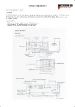
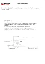
Page 27: ...LCD industry The CA 110 consists of a main unit and a measuring probe The measuring probe utilizes an optical system suitable for measurement of colour LCDs and is equipped with a viewfinder to verify the area to be measured 2 APPLICATIONS White balance adjustment and inspection on LCD production lines Quality control and shipping inspection by LCD manufacturers Inspection of LCDs upon receipt by ...

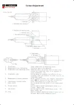
Page 28: ...38 150B3B LCD Go to cover page Colour Adjustment ...

Page 29: ...heck that the POWER switch is set to ON 2 Set the measuring viewing selector to the viewing position An image can be seen in the viewfinder but no light will reach the sensor 3 Press 0 CAL If zero calibration is being performed immediately after the POWER switch has been set to ON press 0 CAL after PUSH 0 CAL KEY appears in the liquid crystal display 4 Set the measuring viewing selector to the pos...

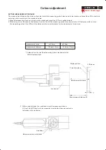
Page 30: ...desired direction until it stops Extending the lens barrel fully sets the 25mm measurement area retracting the lens barrel fully sets the 50mm measurement area Use the screwdriver to tighten the lens barrel locking screw and lock the lens barrel in position Changing the measurement area also changes the measurement angle this may result in differences between values measured with the 25mm measurem...

Page 31: ...g probe s lens barrel to the LCD s display surface move the measuring probe or the LCD until the distance is the correct distance for the measurement area in use o I o I measurement area 25mm 50mm measurement distance 135mm 5mm 210mm 10mm Distance from the tip of the measuring probe s lens barrel to the LCD s display surface LCD panel Lens barrel Display surface Protective glass Measurement distan...

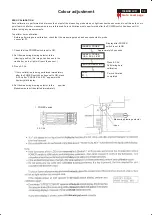
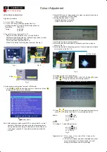
Page 32: ... monitor 5 Adjust OSD menu to lower position of screen i g adjust V position to value 0 at submenu of OSD Setting 6 Setting Brightness and Contrast Adjust Brightness to value100 Adjust Contrast to value 50 7 Switch light probe to Viewing position 8 Move the Lens barrel forward or backward to get clear image as shown in Fig 4 9 Switch light probe to Measuring position It should be able to indicate ...

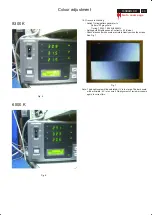
Page 33: ...Hz 48KHz Setting both Brightness and Contrast to 50 Value Check black and white scale are visible clearly across the screen See Fig 7 Fig 7 Note The bright scale will be saturated if Y is too large The dark scale will be invisible if Y is too small Re alignment or review procedure again to correct this Fig 6 Fig 5 9300 K Colour adjustment ...

Page 34: ...n the solder lands by means of litz wire or a solder sucker see Fig 1C 1 3 Caution on removal When handling the soldering iron use suitable pressure and be careful When removing the chip do not use undue force with the pair of tweezers The soldering iron to be used approx 30 W should preferably be equipped with a thermal control soldering o temperature 225 to 250 C The chip once removed must never...

Page 35: ...B HS VS I2C CONTROL SIGNAL CLKH STH POL LP CLKV STV GOE HMS1_0 HMS2_E RX0 1 2 C 6713_RST 6713_IRQ HS VS DDC_A_IIC PANEL PWR CONNECT TO PANEL DDC_D_IIC BL_CTL PANEL_ID BRIGHTNESS DVI_CABLE 5_DVI DSUB_CABLE EEPROM_WP IIC VDDG VEEG VDDA VCOM VDDD PANEL_ID 12V 12V 3 3V R ODD EVEN G ODD EVEN B ODD EVEN HUDSON2 Function Block SCALER SAA6713 CPU P87C51MC2 EEPROM D SUB DVI 74HC4052 KEY LED CTL DDC_D DDC_A...

Page 36: ......

Page 37: ......

Page 38: ......

Page 39: ......

Page 40: ...TGND CGND I013 I012 I009 100R 3231 6220 2215 BAT42W 6222 6219 BAV99 100n 330p 2212 6212 6202 100n 2201 BAV99 BAV99 6203 I007 I008 BAV99 6208 10R 3208 I018 5203 CGND F115 F116 100R F110 6215 BAV99 3226 3 3V BAV99 6216 11 12 13 14 15 2 3 4 5 6 7 8 9 1285 15S 1203 16 17 1 10 TGND I026 3223 100R BAV99 6218 2218 33p F100 2205 100n F106 100n 2214 F108 0R 3233 5201 BAV99 3225 100R 6206 100R 3 3V 3234 0R ...

Page 41: ...30 10K 3437 2 3 4 I033 B8 SCALER BOARD SB 55541 x4 PB 55551 EXCEPT 7402 7403 WERE CHIP COMPONENTS 232270260333 33K 3420 319802131050 3421 319802131030 3422 319802131030 3425 8 I042 E6 I043 E6 12 E D C B A F NI_1 2410 319801731040 2409 319801731040 10K 3437 3412 319802131010 3419 H G F E D C 10 11 12 13 CHN CLASS_NO SUPERS NAME DATE MGr CHECK 3138 158 54421 150S3F 00C MCU A3 10 130 3 02 01 18 YT Li...

Page 42: ... 3VD 47R 3351 47R 3310 2306 47u 2365 33n 47R 3354 I103 33p 2358 I105 I104 1 2 3 4 5 6 7 8 47R 3 3VD 3320 47R 47R 3305 3312 331147R 4 5 6 7 8 100n2381 2V5PLLA 47R 3321 1 2 3 3339 39R 2V5PLLD 2364 33n 27R 3340 5305 47R 3353 100n 2304 AGND 232033p 47R 233033p AGND 100n2391 3307 33p 2345 5313 3V3_6713 5312 33p 2340 2344 33p 33p 2339 5306 33p 2335 33p 2323 6 7 8 33p 2332 332847R 1 2 3 4 5 AGND 100n2383...

Page 43: ...F1 2A 1 2 R0 R 0 BRT_CTL 1 2 3 4 5 7 6 CN3 CONN 86807 0700 ON OFF 1 2 C24 100uF 25V PANEL_ID PANEL_ID 0 0V CPT 3 3V LG 1 2 R50 NC 1 2 CP4 CP 1 2 R51 R 169K 1 2 R54 R 470 1206 N1 N2 N4 N5 N7 N9 N10 N12 N13 N14 N15 N16 N17 N18 N19 N20 N21 N22 N23 N24 N25 N26 N27 N28 N32 N33 N34 N35 N36 N37 N39 N40 N42 N43 N44 N45 N46 N47 N48 N49 N50 VIN N52 1 2 3 47k 47k Q15 DTA144E 1 2 R15 R 1M 1 2 R18 R 1M 1 2 R22...

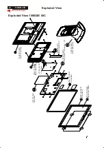
Page 44: ...72901 LCD PANEL 3138 154 04581 Front Bezel 31 40 3138 158 53071 Basic Base Assy 3138 158 54351 Main Frame Wire Assy LG 3138 157 52431 Back Cover Assy 3138 157 52421 Main Shield Assy 1051 1051 3138 158 53541 Scaler Assy 1052 1052 3138 158 54041 Power Assy 1089 1089 3138 188 73471 DC AC INVERTER Exploded View 150B3B 00C ...

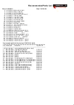
Page 45: ...IRU1206 25CY INR0 R 7303 932218206685 IC SM IRU1206 25CY INR0 R Recommended parts list of Inverter board T501028 00 Ambit Pos Service code Description supplier code 1075 3138 188 73471 DC AC INVERTER T501028 00 Ambit L1 9965 000 12389 COIL A00 0501 DIP AXIS 21 0043 10 F1 9965 000 12390 FUSE KE20 1206 DAITO 26 7040 12 L2 9965 000 12391 IND SPC 1005P 354 SMD TMP 16 0490 01 Q18 9965 000 08856 TR NPN ...

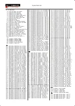
Page 46: ... 3124 319802151020 RST SM 0805 1K PM5 COL R 3125 232273462703 RST SM 0805 RC12H 27K PM1 R 3126 232273462402 RST SM 0805 RC12H 2K4 PM1 R 3127 213811611005 RST MFLM MFR 5S A 1M PM1 A 3128 213811611005 RST MFLM MFR 5S A 1M PM1 A 3129 213811611004 RST MFLM MFR 5S A 1K PM1 A 3130 213811614708 RST MFLM MFR 5S A 4R7 PM1 A 3134 232271161184 RST SM 1206 RC01 180K PM5 R 3135 212266200101 PTC DC 1A85 30V S 0...

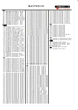
Page 47: ...0603 NP0 50V 33P PM5 R 2361 223886715339 CER1 0603 NP0 50V 33P PM5 R 2362 223886715339 CER1 0603 NP0 50V 33P PM5 R 2363 223878616643 CER2 0603 X7R 16V 33N PM10 R 2364 223878616643 CER2 0603 X7R 16V 33N PM10 R 2365 223878616643 CER2 0603 X7R 16V 33N PM10 R 2366 223878616643 CER2 0603 X7R 16V 33N PM10 R 2367 223878616643 CER2 0603 X7R 16V 33N PM10 R 2368 223878616643 CER2 0603 X7R 16V 33N PM10 R 236...

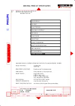
Page 48: ...ES AND 15 USER MODES WHICH CAN BE RECOVERED TO PRESET MODES USER FRIENDLY OSD DISPLAY FOR MODE IDENTIFICATION ADJUSTMENT DDC2B COMMUNICATION CAPABILITY MAX RESOLUTION 1024 x 768 NON INTERLACED AT 75 HZ 15 inches COLOR TFT LCD FLAT PANEL EASY TILT SWIVEL BASE FULL RANGE POWER SUPPLY 90 264 VAC CE ENVIRONMENTAL POLICY ANTI GLARE TO REDUCE LIGHTREFLECTION POWER MANAGEMENTCAPABILITY SOG SYNC SUPPORT T...

Page 49: ...ight 2 8 Functions 2 9 Ambient temperature 2 10 Safety and EMI requirements 3 0 Electrical characteristics 3 1 Interface signals 3 1 1 Video 3 1 2 Interface cable 3 1 3 Software control functions via OSD control 3 2 OSD function control 3 3 Timing requirement 3 3 1 Mode storing capacity 3 3 2 Factory preset timings 3 3 3 Horizontal scanning 3 3 4 Vertical scanning 3 4 Power input connection 3 5 Po...

Page 50: ...Controls 5 2 Unit dimension weight 5 3 Tilt and swivel base 5 4 Transportation packages 5 4 1 Shipping dimension weight 5 4 2 Block unit palletization 6 0 Environmental characteristics 6 1 Susceptibility of display to external environment 6 2 Transportation tests 6 3 Display disturbances from external environment 6 4 Display disturbances to external environment 6 4 1 EMI 7 0 Reliability 7 1 Mean t...

Page 51: ...Ù10 Vertical 9095 degree Horizontal 120115 degree typical Contrast ratio 350 typical Luminance of white 250200 Nits typical Type NR CPT panel CLAA150XG02 Dimensions 326 0 H 252 0 V 11 0 D mm Pitch mm 0 297 x 0 297 mm Color pixel arrangement RGB stripe arrangement Display surface Antiglare with hard coating 3H Number of color 8 bits 16 777 216 colors Backlight CCFL edge light system Active area W x...

Page 52: ... PSB Singapore SEMKO Nordic TUV Germany UL USA GOST Russia B MARK Poland DEMKO Nordic FIMKO Nordic SISIR CPA Singapore EZU Czech EMI requirement BSMI Taiwan C tick Australia CE Europe FCC USA IC Canada VCCI Japan Ergonomic Requirement ISO13406 2 TUV GS TCO99 MPRII Sweden Nutek Sweden Power management EPA Nutek E2000 Environmental Low Emission MPRII TCO99 3 0 Electrical characteristics Compatibilit...

Page 53: ...TNESS CONTRAST Brightness and Contrast adjustment VIDEO NOISE Phase adjustment Clock adjustment ADJUST COLOR Original panel color 9300K for general use 6500k for image management User red green blue adjustable OSD POSITION OSD H position OSD V position PRODUCT INFORMATION show the product information RESET TO FACTORY SETTING recallreturn to Factory preset timings and settings MAIN CONTROLS LANGUAG...

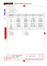
Page 54: ...640 dots E us 0 636 16 dots 0 636 18dots 0 636 16 dots 2 116 64 dots f v 70Hz 70 09 70Hz 70 087 60Hz 59 940 66 7 Hz 66 667 O ms 14 27 449 lines 14 27 449 lines 16 683 525 lines 15 000 525 lines P ms 0 064 2 lines 0 064 2 lines 0 064 2 lines 0 086 3 lines Q ms 1 907 60 lines 1 112 35 lines 1 049 33 lines 1 114 39 lines R ms 11 12 350 lines 12 71 400 lines 15 253 480 lines 13 714 480 lines S ms 1 17...

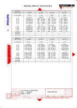
Page 55: ...0 607 23 lines R ms 12 678 480 lines 12 80 480 lines 17 07 600 lines 15 84 600 lines S ms 0 237 9 lines 0 027 1 line 0 028 1 line 0 026 1 line SYNC H V POLARITY SEP SYNC Y Y Y Y MODE NO 9 10 11 12 RESOLUTION 800 x 600 800 x 600 832 x 624 1024 x 768 Dot clock MHz 50 000 49 500 57 280 65 000 f h 48 077kHz 46 875kHz 49 722kHz 48 363kHz A us 20 80 1040dots 21 333 1056dots 20 11 1152dots 20 677 1344 do...

Page 56: ...50 f h 56 476kHz 60 023kHz A us 17 707 1328 dots 16 66 1312dots B us 1 813 136 dots 1 219 96 dots C us 1 920 144 dots 2 235 176 dots D us 13 653 1024 dots 13 003 1024dots E us 0 320 24 dots 0 203 16 dots f v 70 069Hz 75Hz 75 029 O ms 14 272 806 lines 13 328 800 lines P ms 0 106 6 lines 0 050 3 lines Q ms 0 513 29 lines 0 466 28 lines R ms 13 599 768 lines 12 795 768 lines S ms 0 053 3 lines 0 017 ...

Page 57: ... follows STATUS Horizontal Vertical Power Spec LED On Pulse Pulse as normal on Green Stand by No Pulse Pulse 2 W Amber Suspend Pulse No Pulse 2 W Amber Off No Pulse No Pulse 2 W Amber Power switch off is less than 2W 3 6 Display identification In accordance with DVI requirement use DDC2B and EDID 3 0 structure 1 3 1 Input signal As defined in 3 3 1024 x 768 75Hz mode 60 023 KHz Signal sources must...

Page 58: ...K and 6500K Apply full white pattern with brightness in 100 position and the contrast control at 50 The 1931 CIE Chromaticity color triangle diagram x y coordinate for the screen center should be 9300K CIE coordinates X 0 281 0 020 Y 0 311 0 020 6500K CIE coordinates X 0 312 0 020 Y 0 338 0 020 Mode Resolution H freq V freq Standard 1 640 x 350 31 469Khz 70 087Hz VGA 2 720 x 400 31 469Khz 70 087Hz...

Page 59: ...D function key Rear Video signal cable Power cord socket DC 12V fly in USB hub option 5 2 Unit dimension Weight Set dimension incl pedestal 343W x 342H x 165D Net weight 4 3 Kg 5 3 Tilt and swivel base Tilt angle 5 to 25 Swivel rotation 175 5 4 Transportation packages 5 4 1 Shipping dimension Weight Carton dimension 413W x 413H x 220D Gross weight 5 4 Kg 5 4 2 Block unit Palletization layers block...

Page 60: ...e 0 30 000 feet Air pressure 300 1100 mBAR Note recommend at 5 to 35C Humidity less than 60 6 2Transportation tests Standard Philips UAN D1400 NSTA Height 76 0 cm 76 0 cm 1 corner 1 corner Drop Sequence 3 faces 3 edge Test 10deg C x 16 hrs Room temp 6 face Electrical function ok Test Mechanical function ok Result No serious damage on set appearance Room temp 10 degree C humidity 70 1 PACKAGING Seq...

Page 61: ...6 4 1 EMI EMI FCC IC VCCI CE C Tick MPRII BSMI 7 0 Reliability 7 1 Mean time between failures MTBF System MTBF Excluding the LCD panel and CCFL 50 000 hrs CCFL MTBF 30 000 hrs 8 0 Quality assurance requirements 8 1 Acceptance test According to MIL STD 105D Control II level AQL 0 65 major 1 5 minor Please also refer to annual quality agreement 9 0Serviceability The serviceability of this monitor sh...

Page 62: ...LCD GENERAL PRODUCT SPECIFICATION 15 TFT XGA LCD CMTR 150B3B TYPE 150B3B 00C BRAND PHILIPS 8639 000 11911 1 4 02 1 4 02 590 15 17 Y C Liu Go to cover page Fig 1 Brightness and Uniformity Average 5 points average ...

Page 63: ...MTR 150B3B TYPE 150B3B 00C BRAND PHILIPS 8639 000 11911 1 4 02 1 4 02 590 16 17 Y C Liu 71 150B3B LCD Go to cover page D VIDEO C E SEPARATE SYNC HORIZONTAL B A R VIDEO Q S P O D VIDEO C E B A VERTICAL HORIZONTAL COMPOSITE SYNC FIG 2 TIMING CHART 1 ...

Page 64: ...RAL PRODUCT SPECIFICATION 15 TFT XGA LCD CMTR 150B3B TYPE 150B3B 00C BRAND PHILIPS 8639 000 11911 1 4 02 1 4 02 590 17 17 Y C Liu 72 150B3B LCD Go to cover page VIDEO VERTICAL FIG 3 TIMING CHART 2 O P Q R S ...

Page 65: ...or small 1 2 Screen size not correct 3 4 USB 6 7 9 8 10 Unstable picture Picture flickers Out of H V Sync Picture too bright Picture too dim OSD main menu locked 12 13 No power LED is off 15 16 5 11 14 Buzzing sound when power on Missing color Power management function is not active Resolution colors numbers can not be changed Screen color not correct ...

Page 66: ...r type some word with your keyboard to wake up computer from saving status 2 Check that your video cable is plugged in and does not have bent pins Continued If your PC in MS Win 98 and with lots of application software Do not set screen saver Wait at 14 minutes It will cause no dispaly problem as above mentioned Action Restart PC and change timer setting of screen saver ...

Page 67: ... PC END Is picture displayed normally YES It is need to check and repair the monitor NO YES Make sure the correct signal is input Check contrast level is not minimized Press Contrast button increase value to 100 END Is picture displayed normally YES OK NO 1 Make sure the correct signal is input 2 Press the keyboard or operate the mouse 3 Make sure of the range of the input frequency and then set t...

Page 68: ... Choose the Settings tab then click Advanced 5 Choose Monitor button then click Change button 6 Choose Specify the location of the driver Advanced and click the Next button 7 Choose Display a list of all the drivers in a specific location so you can select the driver you want then click Next and then click Have Disk 8 Click Browse button then choose the appropriate drive F CD ROM Drive then click ...

Page 69: ... Adjust Horizontal Vertical Shape Via the monitor On Screen Display or Front Control Knob Auto function key Reset the monitor via OSD manipulation Select Reset to Factory settings END Is picture displayed normally YES NO 3 Consult a service center the monitor may be defective Try the monitor with another computer Video card could be defective ...

Page 70: ...eral Troubleshooting Guide Continued Please contact your dealer reseller for more information OK END NO Picture too Large or Small YES 4 Reset monitor via OSD menu manipulation Change monitor timing to work at the recommended resolution ...

Page 71: ...SB automatically determines resources like driver software and bus bandwidth required by peripherals USB makes necessary resources available without user intervention It is designed to meet Microsoft Plug and Play PnP specification meaning users can install and hot swap devices without long installation procedures and reboots It allows 127 devices to run at the same time on the bus USB bus provide...

Page 72: ...e Continued Please contact your dealer reseller for more information OK END NO Unstable Picture Picture Flickers YES Vertical Horizontal flicker appears Push the AUTO button Eliminate the vertical horizontal bars using the Phase Adjustment in the FIRST Window 6 ...

Page 73: ...etting timing range or Sync problem 1 Try system with another monitor 2 Try monitor with another system Monitor related YES It is need to check and repair the monitor NO Make sure that the Video system doesn t select a driver that is outside the Monitor H V scan range out of presetting timing range while going into windows Run Windows by us ing ba s ic VG A m ode Exa m ple 640 x 480 H V out of pre...

Page 74: ...t Control Knob END Is picture displayed normally YES It is need to check and repair the monitor NO Reset the monitor via OSD manipulation Select Reset to Factory settings or Change the color temperature settings to be 9300 color coordination from OSD menu Try the monitor with another computer Video card could be defective END Is picture displayed normally YES NO 8 ...

Page 75: ...layed normally YES Reset the monitor via OSD manipulation Select Reset to Factory settings or Change the color temperature settings to be 9300 color coordination from OSD menu Try the monitor with another computer Video card could be defective END Is picture displayed normally YES NO NO 9 Note 1 Sun light passing through a window is much brighter than monitor luminance Luminance is the measurable ...

Page 76: ...t unit is plugged into a known good power source Move a good radio to plug into the power source to test it Power off the monitor and then on POWER LED ON It is need to check and repair the monitor It is need to check and repair the monitor NO YES POWER LED ON END YES NO 1 Is the correct AC power cord connected 2 Is AC power outlet active 3 Is the power button in the ON position YES YES NO 10 YES ...

Page 77: ...e produced 2 View an image that supposed to contain Red Green and Blue Color problems will be apparent when one or more of these colors can not be displayed 1 Turn off monitor 2 Disconnect video cable 3 Turn on monitor Is picture displayed normally It is need to check and repair the monitor Colors on warning signal OK YES Check video cable for bent pins reseat it END YES Signal cable pins OK YES 1...

Page 78: ...General Troubleshooting Guide Continued Please contact your dealer reseller for more information OK END NO OSD MAIN MENU LOCKED YES Press and hold the OSD menu key for about 10 seconds until picture displays OSD MAIN MENU UNLOCKED 12 ...

Page 79: ...th another monitor 2 Try monitor with another system Monitor related Jitter or Noise disappear END YES NO Video system problem It is need to check and repair the monitor Power off any monitor that is within 2 or 3 feet away Remove any unshielded speakers away from the monitor Make sure there are no flourescent light fixtures close to the monitor Try to keep monitor away from large metal structures...

Page 80: ...not active Verify the PC is compliant with VESA In case all of the video signals of PC are not off power management function is not active normally Repeat to power on and off power management There are accelerator boards not complied with VESA YES 14 Consult a service center the monitor may be defective END ...

Page 81: ...ocedure or tool which is not recommended by Philips must first satisfy himself thoroughly that neither his safety nor the safe operation of the equipment will be jeopardized by the service method selected Hereafter throughout this manual Philips Consumer Electronics Company will be referred to as Philips WARNING Critical components having special safety characteristics are identified with a by the...

Page 82: ...Portrait display 90 rotation counter colockwise o o Forward Backward 5 25 AC input voltage frequency 90 to 264 VAC 50 or 60 Hz Power consumption 23 W typ Temperature Operating 5 C to 40 C 41 F to 104 F Humidity Operating 20 to 80 System MTBF 50K Hrs CCFL 40Khrs Technical Specifications Pin Assignment Technical Data DVI D connector Digital Visual Interface Digital Go to cover page Pin Assignment Th...

Page 83: ...reen Amber Blanked Blanked Blanked 3 W 90 83 3 83 3 0 3 W 3 W 23 W Suspend ON OFF No No No No Yes Yes Yes Yes Stand by V SYNC POWER SAVING POWER USED LED COLOR H SYNC VIDEO VESA s mode This monitor is Environmental Protection Agency EPA Energy Star compliant and TCO 99 power management compatible Zero power consumption in OFF mode can only be achieved by disconnecting the mains cable from the moni...

Page 84: ...re 2 Put to both thumbs on the top of base and other fingers on upper area of the recess on the back cover As attached picture 1 Turn off your computer and unplug its power cable 2 Connect the monitor signal cable to the video connector on the back of your computer 3 Plug the power cord of your computer and your monitor into a nearby outlet 4 Turn on your computer and monitor If the monitor displa...

Page 85: ...or transportation 5 Do not store or use the LCD monitor in locations exposed to high humidity or a dusty environment Also do not allow water or other liquids to spill on or into the LCD monitor Correct handling of the monitor 1 When handling the monitor grip the bottom firmly with both hands and ensure that the front panel faces outward before lifting Please refer to the diagram on the right 2 Han...

Page 86: ...row buttons are pressed the adjustment controls for the BRIGHTNESS will show up OK button which when pressed will take you to the OSD controls POWER button switches your monitor on Automatically adjust the horizontal position vertical position phase and clock setting Physical Function 1 Tilt 2 Swivel 3 Height adjustment 4 Pivot 4 1 Tilt the monitor body at an angle 4 2 Rotate the monitor body 90 d...

Page 87: ...ess and mute expectively while OSD locked Locked OSD function can be released by pressing button for more than 10 seconds While press button for OSD unlocked purpose the screen will keep showing OSD MAIN MENU LOCKED until OSD function unlocked and screen automatically shows following window for 3 seconds Switch ON OFF attention signals All attention signals can be switched off by keep pressing but...

Page 88: ...e optimal video display of LCD monitor Following steps will guide you to make correct adjustment of CLOCK and PHASE However CLOCK and PHASE functions are only available while analog video signal is supplied Operating unit under digital signal state the video clock information can be obtained from graphics cards directly Therefor it is unnecessary to adjust these functions Auto adjustment hotkey Ma...

Page 89: ...Tree for analog video signal Below is an overall view of the structure of the On Screen Display You can use this as reference when you want to later on work your way around the different adjustments Go to cover page OSD Menu Analog First Level Second Level ...

Page 90: ...SD Tree for digital video signal DVI D or DVI I This OSD structure is different from analog menu there are three functions will be disable on digital OSD menu Contrast Video Noise and Adjust Color Go to cover page First Level Second Level OSD Menu Digital ...

Reviews: