EN 75
TMP1.0U LA
8.
8.2
Service Tools
8.2.1
ComPair
Introduction
ComPair (Computer Aided Repair) is a Service tool for Philips
Consumer Electronics products. and offers the following:
1.
ComPair helps you to quickly get an understanding on how
to repair the chassis in a short and effective way.
2.
ComPair allows very detailed diagnostics and is therefore
capable of accurately indicating problem areas. You do not
have to know anything about I
2
C or UART commands
yourself, because ComPair takes care of this.
3.
ComPair speeds up the repair time since it can
automatically communicate with the chassis (when the uP
is working) and all repair information is directly available.
4.
ComPair features TV software upgrade possibilities.
Specifications
ComPair consists of a Windows based fault finding program
and an interface box between PC and the (defective) product.
The (new) ComPair II interface box is connected
to the PC
via
an USB cable. For the TV chassis, the ComPair interface box
and the TV communicate via a bi-directional cable via the
service connector(s).
How to Connect
This is described in the ComPair chassis fault finding database.
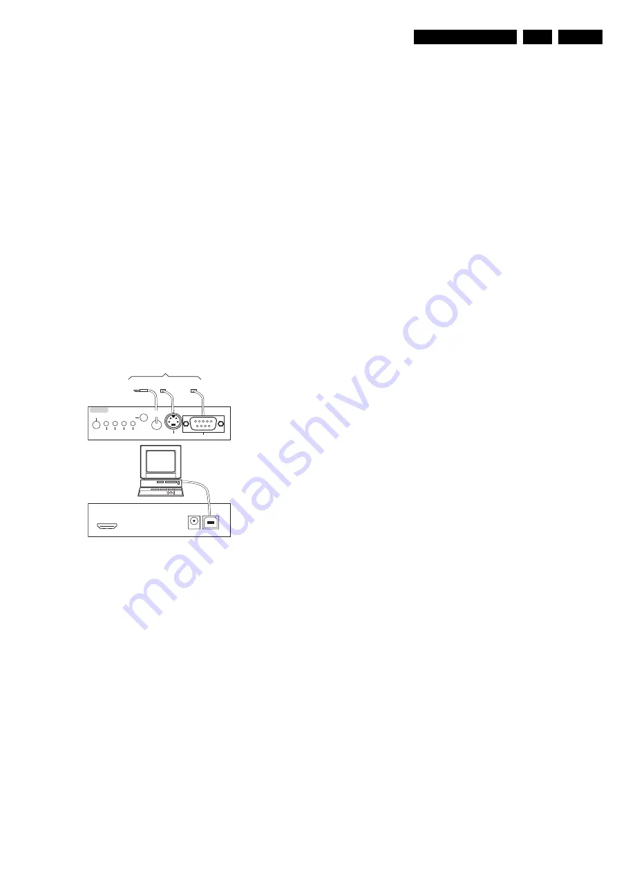
Figure 8-1 ComPair II interface connection
Caution:
It is compulsory to connect the TV to the PC as
shown in the picture above (with the ComPair interface in
between), as the ComPair interface acts as a level shifter. If
one connects the TV directly to the PC (via UART), ICs will be
blown!
How to Order
ComPair II order codes:
•
ComPair II interface: 3122 785 91020.
•
ComPair32 CD (update): 3122 785 60160.
•
ComPair I
2
C interface cable: 3122 785 90004 (to be used
with chassis L01, A02, A10, EMx, TPM1.xA, etc ...).
•
ComPair I
2
C interface extension cable: 3139 131 03791 (to
be used with chassis L01, A02, A10, L04, LC4, LC7.1,
LC7.2).
•
ComPair UART interface cable: 3122 785 90630 (to be
used with chassis LC4, EJ3, BJ2, BL2, BP2, ...).
•
ComPair RS232 cable: 3104 311 12742 (to be used with
chassis Q52x).
•
ComPair I
2
C interface cable (3.5 mm Jack-to-SVHS plug):
9965 100 07325 (to be used with chassis LC7.5).
Note:
For I
2
C it is
compulsory
to use this particular cable.
•
ComPair UART interface cable (3.5 mm Jack-to-Jack):
3138 188 75051 (to be used with chassis LC7.5).
Note:
For UART it is also allowed to use a standard “Jack-
to-Jack” cable.
Note:
If you encounter any problems, contact your local
support desk.
8.2.2
LVDS Tool
Support of the LVDS Tool has been discontinued.
G_06532_036.eps
240807
TO
UART SERVICE
CONNECTOR
TO
UART SERVICE
CONNECTOR
TO
I2C SERVICE
CONNECTOR
TO TV
PC
HDMI
I
2
C only
Optional power
5V DC
ComPair II Developed by Philips Brugge
RC out
RC in
Optional
Switch
Power
Mode
Link/
Activity
I
2
C
ComPair II
Multi
function
RS232 /UART
Summary of Contents for 19PFL5402D/27
Page 2: ......
Page 43: ...41 TPM1 0U LA 7 Circuit Diagrams and PWB Layouts Scaler Board Layout Top Side Part 1 ...
Page 44: ...42 TPM1 0U LA 7 Circuit Diagrams and PWB Layouts Scaler Board Layout Top Side Part 2 ...
Page 45: ...43 TPM1 0U LA 7 Circuit Diagrams and PWB Layouts Scaler Board Layout Top Side Part 3 ...
Page 46: ...44 TPM1 0U LA 7 Circuit Diagrams and PWB Layouts Scaler Board Layout Top Side Part 4 ...
Page 89: ...10 31 TPM1 0U LA 87 9 Circuit Descriptions Abbreviations List and IC Data Sheets ...
Page 141: ...39 TPM1 0U LA 7 Circuit Diagrams and PWB Layouts Scaler Board Layout ...
Page 142: ...40 TPM1 0U LA 7 Circuit Diagrams and PWB Layouts Scaler Board Layout TOP LEFT ...
Page 143: ...41 TPM1 0U LA 7 Circuit Diagrams and PWB Layouts Scaler Board Layout TOP RIGHT ...
Page 144: ...42 TPM1 0U LA 7 Circuit Diagrams and PWB Layouts Scaler Board Layout BUTTOM LEFT ...
Page 145: ...43 TPM1 0U LA 7 Circuit Diagrams and PWB Layouts Scaler Board Layout BUTTOM RIGHT ...
Page 146: ...44 TPM1 0U LA 7 Circuit Diagrams and PWB Layouts Scaler Board Layout 2 ...
Page 147: ...45 TPM1 0U LA 7 Circuit Diagrams and PWB Layouts Scaler Board Layout 2 TOP LEFT ...
Page 148: ...46 TPM1 0U LA 7 Circuit Diagrams and PWB Layouts Scaler Board Layout 2 TOP RIGHT ...
Page 149: ...47 TPM1 0U LA 7 Circuit Diagrams and PWB Layouts Scaler Board Layout 2 BUTTOM LEFT ...
Page 150: ...48 TPM1 0U LA 7 Circuit Diagrams and PWB Layouts Scaler Board Layout 2 BUTTOM RIGHT ...
Page 191: ...89 TPM1 0U LA 9 Circuit Descriptions Abbreviations List and IC Data Sheets ...


