Mechanical Instructions
EN 8
LC4.9U AA
4.
quick and easy with use of the delivered screws that can be
tightened and loosened manually without the use of tools. See
figure above.
Note:
Only use the delivered screws to mount the monitor to
the stands.
4.3
Assy/Panel Removal
4.3.1
Metal Rear Cover
Caution:
Disconnect the Mains/AC Power cord before you
remove the rear cover!
1.
Place the TV set upside down on a table top, using the
foam bars (see part "Foam Bars").
Caution:
do
not
put pressure on the display, but let the
monitor lean on the speakers or the Front cover.
2.
Remove all T10 screws around the edges of the metal rear
cover: “parker” screws around the outer rim, “tapping”
screws around the connector plate.
3.
Remove the four "mushrooms" from the rear cover.
4.
Lift the metal rear cover from the set. Make sure that wires
and flat foils are not damaged.
4.3.2
Speaker Compartment Cover
After removing the metal rear cover, you gain access to the
Speaker Compartment covers.
1.
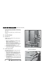
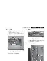
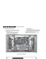
Remove all T10 screws [1] around the outer rim of the
cover (see Figure “Speaker compartment cover removal”).
2.
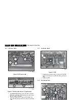
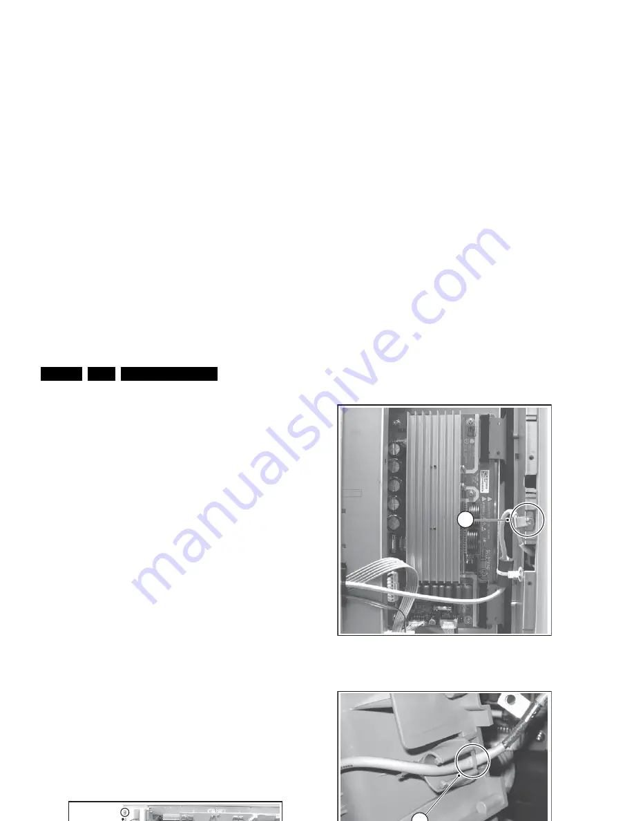
Remove the T10 screws [2] on top of the inner rim,
including the one which secures the grounding clamp (3,
see Figure “Grounding clamp”).
3.
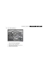
Now, remove the plastic cable fixation noose (4, see Figure
“Cable fixation noose”).
4.
After removal of all the screws, slightly push the top of the
cover inwards. This will lift the outer rim slightly up so you
can take the cover out.
Figure 4-4 Speaker compartment cover removal
Figure 4-5 Grounding clamp
Figure 4-6 Cable fixation noose
F_15430_045.eps
100605
1
2
F_15430_046.eps
100605
3
F_15430_047.eps
100605
4


