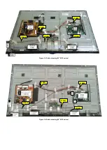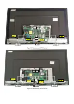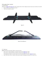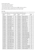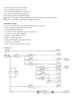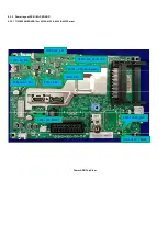
Figure 3-21 (For 24” 4022 series)
Figure 3-22(For 32” 4112 series)
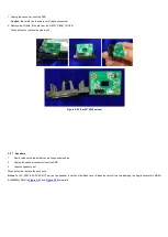
3.2.8 WIFI module
1. Unplug the connector from the SSB..
2. Remove fixation screw that secure the WIFI module,
When defective, replace the whole unit.
3.2.9 LCD Panel
Remove the SSB as described earlier.
Remove the keyboard control panel as described earlier.
Remove the stand bracket as described earlier.
Remove the IR/LED as described earlier.
Remove the fixations screws that fix the metal clamps to the front bezel. Take out those clamps.
Remove all other metal parts not belonging to the panel.
Lift the LCD Panel from the bezel.
When defective, replace the whole unit.
Summary of Contents for 32PFS4132/12
Page 3: ...Product Information ...
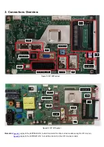
Page 10: ...Figure 3 11 For 4232 4132 4032 series Figure 3 12 For 4112 series ...
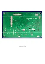
Page 30: ...Power SSB Bottom View ...
Page 36: ...7 IC Data Sheets 7 1NT72461MBG PA IC U401 ...
Page 37: ...7 2 W29N01GVSIAA IC U405 ...
Page 38: ...7 3 TAS5753MDDCAR IC U601 ...
Page 109: ...8 14 715G7088 KEY For 32 43 49 4132 Series 32 4032 Series 8 14 1 KEY ...
Page 112: ...9 2 4132 4032 series 32 0040 1054 050R 050L 1050 0030 1053 1184 1056 1057 0036 0063 ...
Page 113: ...9 3 4132 series 43 0030 1056 050R 050L 0040 0063 1054 1053 1050 1057 1184 0036 0047 ...
Page 114: ...9 4 4132 series 49 0030 1056 050R 050L 1184 0040 0063 1054 1053 1050 1057 1184 0036 0047 ...
Page 115: ...9 5 4112 series 32 0030 1056 050R 050L 0040 1052 1184 1050 ...
Page 116: ...9 6 4112 series 39 0030 1056 050R 050L 1184 0040 1052 1184 1050 ...
Page 117: ...9 7 4112 series 43 0030 1056 050L 0040 1052 1050 1184 050R ...
Page 118: ...9 8 4032 series 24 4022 series 22 24 0030 1054 0040 1053 1050 1184 5050 0036 1056 ...


