Circuit Descriptions
7.
7.4
Circuit Description
7.4.1
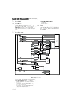
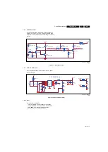
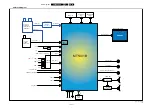
System power
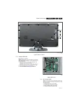
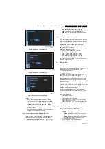
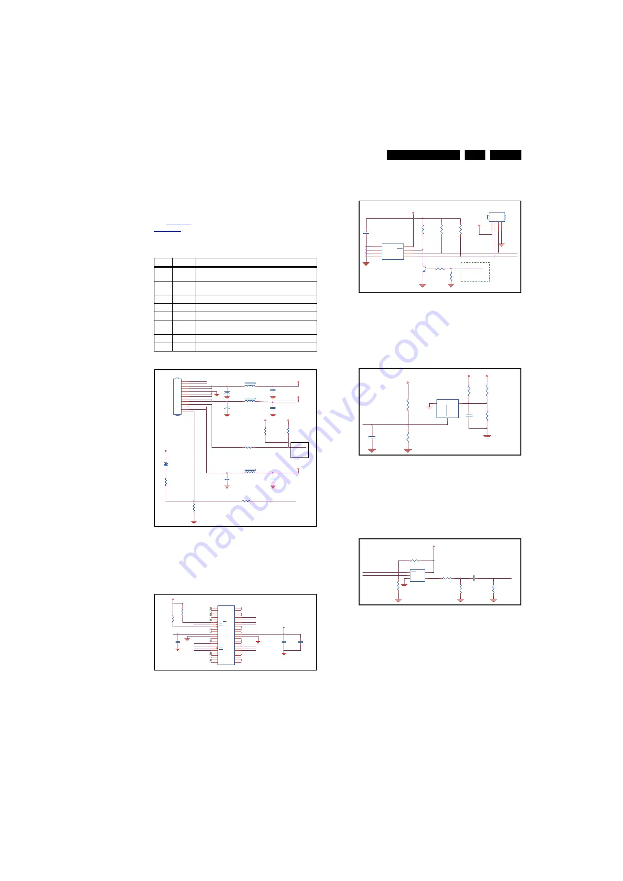
The main board power is received at connector CN701 from
power board, to receive the power and signals from the PSU.
See
for the correct pining, The shown test points in
.
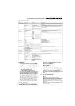
Table 7-1 Connector CN701 overview
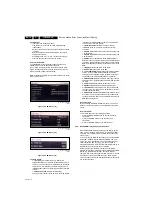
Figure 7-4 System power
7.4.2
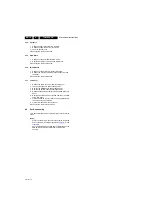
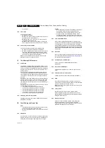
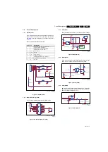
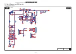
Nand flash Memory (U403)
The set uses a 128 MB NAND flash for software code
Figure 7-5 Nand flash Memory (U403)
7.4.3
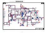
NVM (U405)
The system NVM is a 128 KB IC. It contains all system settings.
Figure 7-6 NVM (U405)
7.4.4
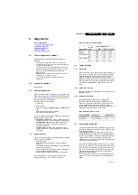
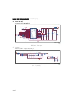
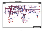
Reset (U406)
When the input voltage for the MT5301B main processor drops
below 2.93 V, a system reset will be enforced by U406.
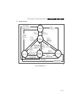
Figure 7-7 Reset (U406)
7.4.5
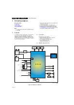
ARC (HDMI)
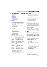
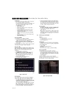
ARC (audio return channel) supports HDMI A only, if it gets the
ARC command from CEC, then the U412 will be enable and
SPDIF will output via HDMI A pin 14.
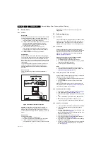
Figure 7-8 ARC (HDMI)
Item
Pin
Description
1
1
INVERTER_ON_OFF, Inverter board
control (Low: ON, High: OFF)
2
2
BRIGHT_ADJ, Inverter bright PWM
control (Max.: 0 V, Min.: 3V3)
3
3, 4
+12 V Supply
4
5, 6, 7
Ground
5
8, 9
+24 V Supply
6
10
STANDBY, Standby
control (High: Normal, Low: Stand by)
7
11, 12
STB_PWR5V, +5VSB Supply
8
13
LED ON
19170_208_110705.eps
110705
PWR_OK
BL_CTRL
BRI_ADJ
STANDBY
5VSB
+12V
+24V
DVDD3V3
5V_SW
+12V
H : ON
L : Standby
1
2
3
4
5
6
7
8
9
10
11
12
13
CN701
CONN
CN701
CONN
+
C705
100UF 25V
+
C705
100UF 25V
1
2
FB702
120R/6000mA
FB702
120R/6000mA
C706
10U 10V
C706
10U 10V
R765
NC\1K 1/16W 5%
R765
NC\1K 1/16W 5%
1
2
ZD139
RLZ5.6B
ZD139
RLZ5.6B
1
2
FB701
120R/6000mA
FB701
120R/6000mA
R769
1K2 1/10W 5%
R769
1K2 1/10W 5%
R750
0R05 1/10W
R750
0R05 1/10W
+
C701
100UF 25V
+
C701
100UF 25V
R764
NC\1K 1/16W 5%
R764
NC\1K 1/16W 5%
R701
1.2K 1/16W
R701
1.2K 1/16W
C702
100N 50V
C702
100N 50V
+
C703
100UF 35V
+
C703
100UF 35V
1
2
FB703
120R/6000mA
FB703
120R/6000mA
C704
100N 50V
C704
100N 50V
R712
0R05 1/10W
R712
0R05 1/10W
19170_211_110705.eps
110720
DVDD3V3
C460
100N 16V
DVDD3V3
PDD7
PDD6
R472
4K7 1/16W 5%
PDD5
PACLE
NC23
39
NC1
1
NC2
2
NC3
3
NC4
4
NC5
5
NC26
46
ALE
17
CLE
16
WE
18
NC17
26
NC8
11
WP
19
RY /BY 1
7
NC9
14
NC10
15
NC18
27
NC19
28
NC11
20
NC12
21
NC13
22
I/O3
32
NC20
33
VSS2
36
VCC1
12
RE
8
VCC2
37
I/O2
31
I/O1
30
I/O0
29
VSS1
13
NC25
45
I/O7
44
I/O6
43
I/O5
42
I/O4
41
NC24
40
NC14
23
NC15
24
NC16
25
CE1
9
NC21
34
NC22
35
NC27
47
PRE
38
NC6
6
NC7
10
NC28
48
U403
H27U1G8F2BTR-BC
DVDD3V3
DVDD3V3
PAALE
SMD/0402
SMD/0402
PDD4
POWE#
PDD2
PARB#
FLASH_WP#
PDD3
PDD1
POOE#
PDD0
C462
10U 10V
POCE1#
C461
100N 16V
R473
4K7 1/16W 5%
19170_212_110705.eps
110705
1
2
3
4
CN402
NC CONN
Q401
PMBS3904
DVDD3V3
R462
4.7K 1%
R463
4.7K 1%
5VSB
R465
10K 1/16W 5%
VSS
4
VCC
8
SDA
5
SCL
6
E0
1
E1
2
E2
3
WC
7
U405
CAT24C128Y I
R464
2.2K 1/16W
C454
220N16V
I2C address at A0
OSCL0
MEMORY _WP#
R461
10K 1/16W 5%
OSDA0
H: Write
L: Write Protect
19170_213_110705.eps
110705
R471
NC 6K8 1/10W 1%
5VSB
R470
NC 1K 1/10W 1%
GND
1
RE
S
ET
2
VCC
3
U406
MAX809STRG
R468
100K 1/16W
R467
NC\5K1 1/16W 5%
3V3SB
R469
0R05 1/16W
C456
100N 16V
C455
NC\100N 16V
3V3SB
ORESET#
19170_216_110705.eps
110718
R569
10K 1/16W 5%
R572
82R 1/10W 5%
C511
1UF16V
OE
1
A
2
GND
3
Y
4
VCC
5
U412
SN74LVC1G125DBVR
SPDIF_OUT
R571
180OHM 1/10W
ARC
R573
100K 1/10W 5%
ARC_ON
DVDD3V3
R570
NC\10K 1/16W 5%

