Circuit Descriptions
7.
7.4.8
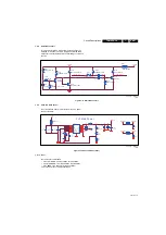
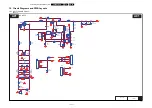
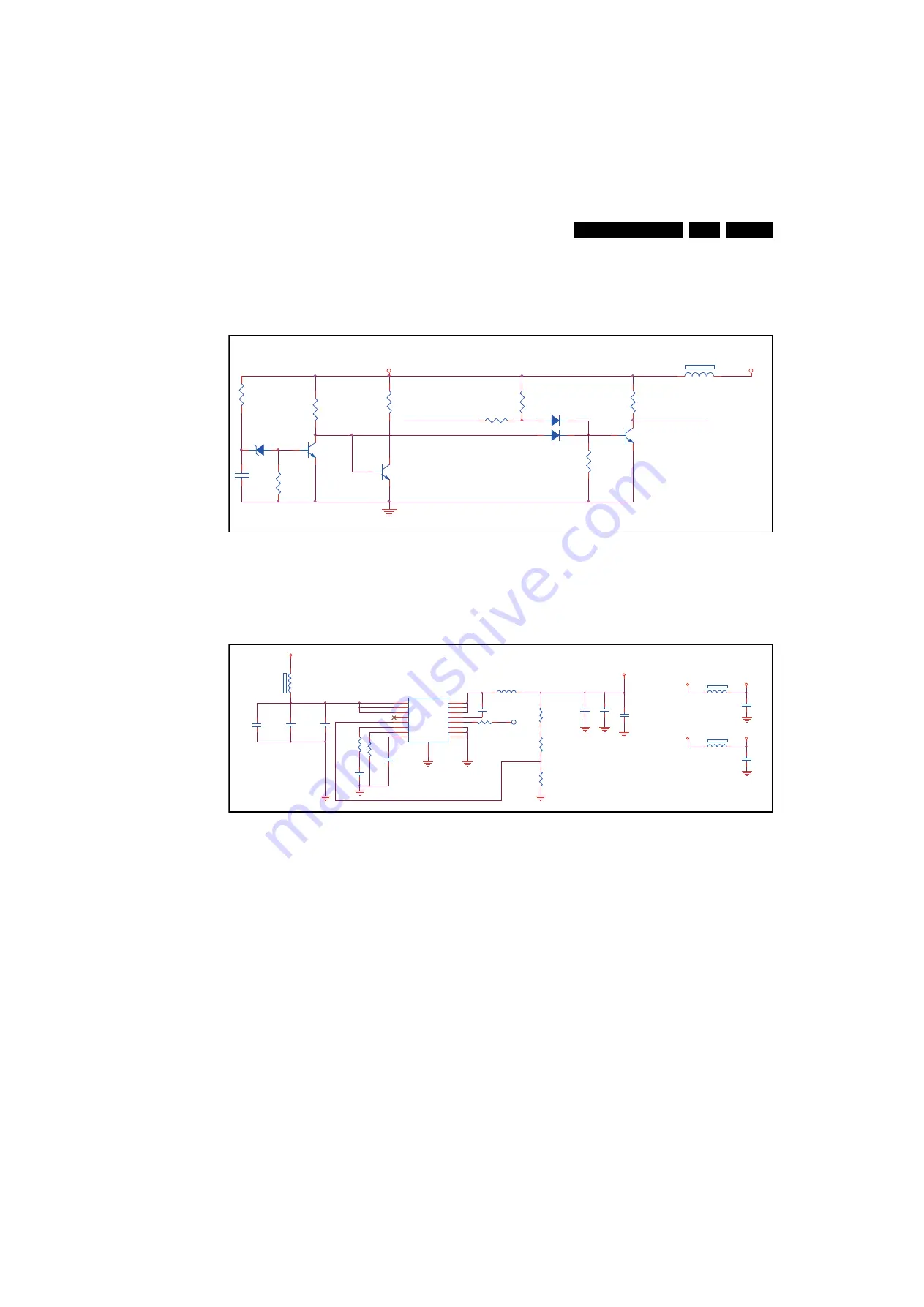
Audio Mute circuit
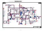
This circuit will provide a “high-to-low” pulse when the +5 V
SSB power line goes low. This will trigger the related audio
mute circuit, preventing the audio circuit making uncontrolled
sounds.
Figure 7-11 Audio Mute circuit
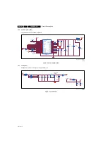
7.4.9
AV33 and DV33 (U701)
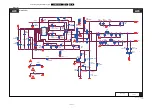
The circuit around U701 will provide the main 3.3 V power
supply to the SSB.
Figure 7-12 AV33 and DV33 (U701)
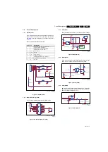
7.4.10 Tuner
The tuner covers as followed:
•
VHF LOW BAND: from 49.75 MHz to 144.25 MHz.
•
VHF HIGH BAND: from 1526.25 MHz to 448.25 MHz.
•
UHF BAND: from 456.25 MHz to 863.25 MHz.
I
2
C bus control of tuner, address selection.
19170_215_110705.eps
110718
5V_SW
1
2
FB601
120R/6000mA
1
3
2
Q603
NC PDTC114ET
R610
4K7 1/16W 5%
R609
10K 1/16W 5%
R602
NC 10K 1/16W 5%
POP_MUTE
D601
LL4148
D602
LL4148
+5V_ON
MUTE_CTL
R608
1.8KOHM 1/10W
R607
100R 1/16W 5%
1
3
ZD601
BZX84C3V6
R603
1.8KOHM 1/10W
C684
10uF 10V
Q602
BC847C
R601
100K 1/10W 5%
R611
4-5% 1/10W
Q601
BC847C
19170_209_110705.eps
110705
3V3 Main Power
1
2
FB717
120R/3000mA
C723
1UF 10V
C722
1UF 10V
1
2
FB716
120R/3000mA
3V3_BUCK
DVDD3V3
AVDD3V3
3V3_BUCK
1
2
FB715
120R/6000mA
R729
1
8
0K 1
%
VIN
1
VIN
2
GND
3
GND
4
AGND
5
VSNS
6
COMP
7
RT/CLK
8
SS
9
PH
10
PH
11
PH
12
BOOT
13
PWRGD
14
EN
15
VIN
16
Pw
Pd
17
U701
TPS54319RTE
C713
3.3nF 50V
R730
300R 1/16W 1%
C720
22uF 10V
R767
100K 1%
C738
0.1UF 16V
L701
1.5UH
TP708
R728
7K5 1/
16W
5
%
C719
NC/22uF 10V
C721
22uF 10V
R766
33K 1%
R772
100K 1/16W 5%
C799
0.1UF 16V
C717
10uF 10V
C718
100N 16V
C7001
100N 16V
3V3_BUCK
5V_SW

