

10.
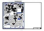
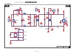
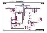
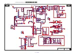
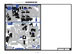
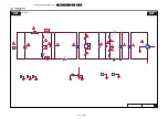
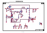
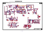
Circuit Diagrams and PWB Layouts
10-7-2
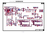
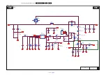
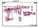
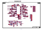
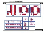
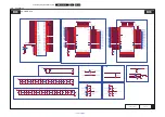
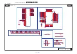
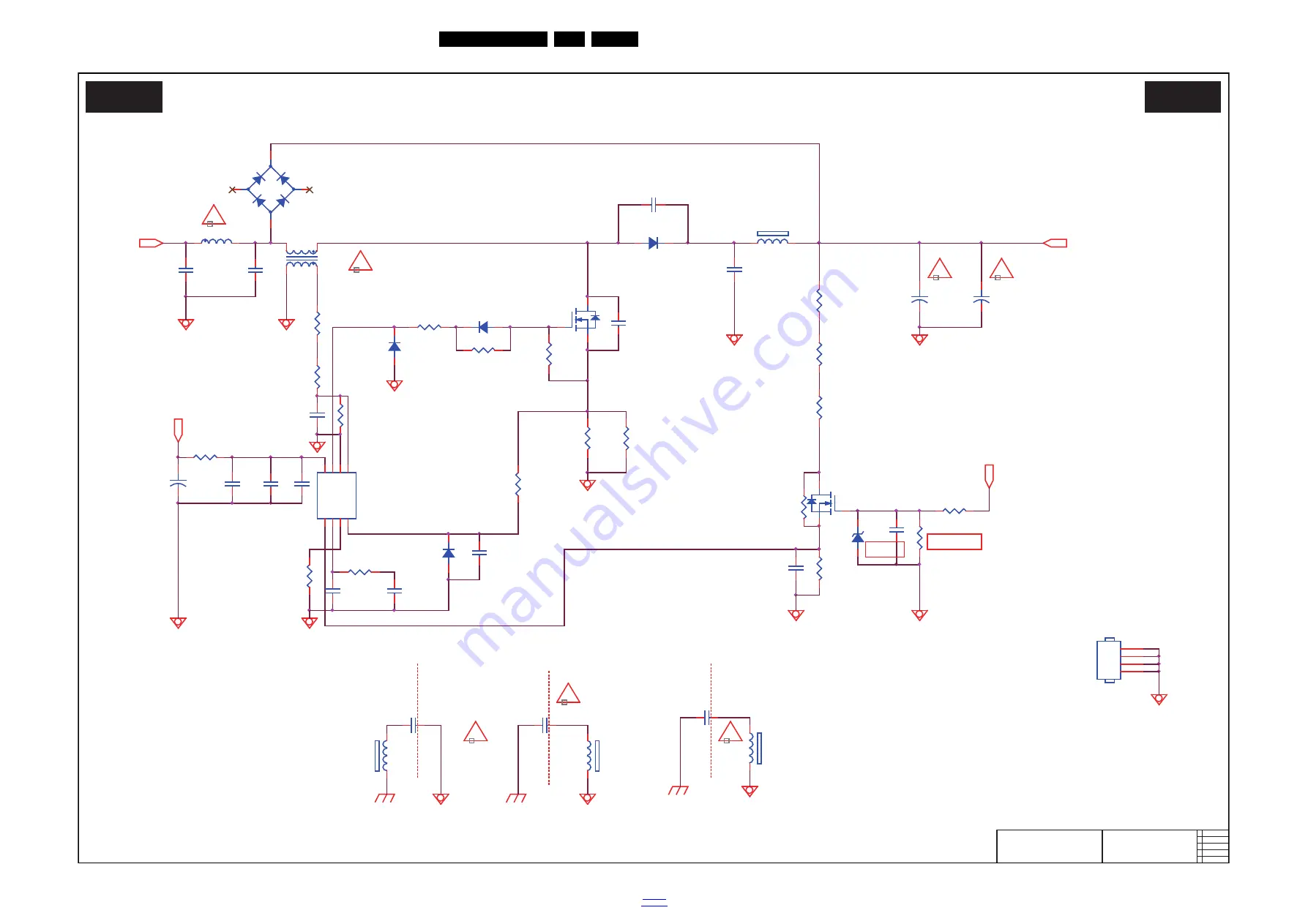
PFC LD7591T
20030_501.eps
PFC LD7591T
A02
A02
2015-11-05
715G7720
PFC LD7591T
R9817
10K OHM
R9807
2KOHM +-1% 1/8W
C9820
470PF 250V
!
R9813
27K +-1% 1/8W
C9818
680PF 250V
!
FB9802
BEAD
1
2
HS9801
HEAT SINK
1
2
3
4
C9814
100N 50V
R9819
0R05 1/4W
R9815
30K 1/8W 1%
C9815
100N 50V
C9816
100N 50V
C9817
100PF
D9805
SS1060FL
D9806
SS1060FL
R9818
NC
C9813
0.47UF 50V
C9809
100N 50V
C9812
47N 50V
R9812
470R 1%
+
C9808
22UF 50V
C9806
1UF 450V
C9807
47P 50V
+
C9803
82uF 450V
R9802
33ohm 1/4W +/-5%
R9814
10K 1/8W
+
C9804
82uF 450V
Vsin
D9804
SS1060FL
R9805
10K 1/8W
D9802
FMNS-1106S
C9801
47PF
U9801
LD7591T
INV
1
CO
MP
2
RA
MP
3
C
S
4
ZCD
5
GN
D
6
OU
T
7
VC
C
8
C9810
470PF 50V
C9811
1NF
R9803
56 OHM +-5% 1/4W
Vbus
R9804
1M 1% 1/4W
R9811
19K1 +-1% 1/8W
R9801
0R05
R9806
1M 1% 1/4W
R9810
1M 1% 1/4W
+VCC2
+VCC2
FB9805
BEAD
1
2
Q9801
IPA60R125P6
2
1
3
R9816
100K 1/8W 1%
FB9803
BEAD
1
2
R9808
0.15R
Q9802
BSS127
3
1
2
R9809
0.15R
C9821
220PF 250V
FB9804
BEAD
1
2
!
C O L D
H O T
!
!
!
!
L9802
120uH
C9802
10NF 1KV
-
+
BD9801
KBP208G-C
2
1
3
4
L9801
200uH
6
4
1
3
C9819
1UF 450V
C O L D
H O T
ZD9802
BZT52-B18
1
2
C O L D
H O T


