* If you are using an antenna, make sure it is not broken or shorted, and make sure the antenna cable is
connected properly and securely.
* If you are using a VCR and selecting channels on the TV, make sure the TV/VCR mode on the VCR is
set to TV.
The picture has no colors or colors are not correct.
* Make sure you have made connections correctly.
* If you have connected accessory equipment, such as an HD satellite receiver, make sure the color setting
on the accessory equipment is correct. See the user manual for the HD satellite receiver.
The TV sound has an unusual quality.
* Check the TV's Equalizer control to be sure it is set to the option you want.
Remote-related Checks
The remote control does not work.
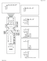
* Make sure nothing is blocking the path between the remote control and the TV or accessory device you
want to operate.
* Make sure you point the remote directly at the TV or accessory device you want to operate.
* If you want to operate the TV, make sure the remote is in TV mode. If you want to operate an accessory
device, program the remote for the device if necessary and make sure the remote is in the appropriate
mode for the device.
* Make sure you have installed the batteries correctly.
* The batteries could be dead. When the batteries in the remote run low, the remote will send a "Battery
Low" command to the TV.
The TV will then display a message on the screen reminding you to replace the batteries as soon as
possible.
* You may want to try taking the remote batteries out and putting them back in. NOTE: After taking the
batteries out, you may need to reprogram the remote for use with accessory devices.
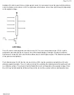
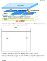
Reflective LCD Introduction.
The LCOS (Liquid Crystal on Silicon) uses a reflective LCD system. A single reflective LCD panel with
Page 12 of 15
2004-08-09
Summary of Contents for 55PL9524/37
Page 10: ...Page 9 of 15 2004 08 09 ...
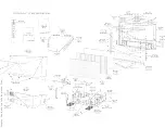
Page 23: ...Display The Main Cabinet Exploded View ...
Page 34: ......
Page 35: ......
Page 36: ......
Page 37: ...IIC BUS SIGNAL DIAGRAM ...
Page 39: ......
Page 40: ......
Page 41: ......
Page 42: ......
Page 43: ......
Page 44: ......
Page 45: ......
Page 46: ......
Page 47: ......
Page 48: ......
Page 49: ......
Page 50: ......
Page 51: ......
Page 52: ......
Page 53: ......
Page 54: ......
Page 55: ......
Page 56: ......
Page 57: ......
Page 58: ......
Page 59: ......
Page 60: ......
Page 61: ......
Page 62: ......
Page 63: ......
Page 64: ......
Page 65: ......
Page 66: ......
Page 67: ......
Page 68: ......
Page 69: ......
Page 70: ......
Page 71: ......
Page 72: ......
Page 73: ......
Page 74: ......
Page 75: ......
Page 76: ......
Page 77: ......
Page 78: ......
Page 79: ......
Page 80: ......
Page 81: ......
Page 82: ......
Page 83: ......
Page 84: ......
Page 87: ... W INPUT POWER PANEL Bottom View Return to Circuit Board TOC ...
Page 89: ... U1 MAIN POWER PANEL Bottom View Return to Circuit Board TOC ...
Page 91: ... K SYSTEM BOARD Bottom View Return to Circuit Board TOC ...
Page 92: ...Refer to the next page for Bottom Side View B SSB PANEL Top View Return to Circuit Board TOC ...
Page 93: ... B SSB PANEL Bottom View Return to Circuit Board TOC ...
Page 95: ... SL SCALER PANEL Bottom View Return to Circuit Board TOC ...
Page 97: ... F DW PIP PANEL Bottom View Return to Circuit Board TOC ...
Page 99: ... CB1 3D COMB FILTER PANEL Bottom View Return to Circuit Board TOC ...
Page 101: ... V REAR JACK PANEL Bottom View Return to Circuit Board TOC ...
Page 103: ... O1 SIDE JACK PANEL Bottom View Return to Circuit Board TOC ...
Page 105: ... LS LED SENSOR PANEL Bottom View Return to Circuit Board TOC ...
Page 107: ... P1 LED KEYBOARD PANEL Bottom View Return to Circuit Board TOC ...
Page 109: ... TS1 THERMAL SENSOR PANEL Bottom View Return to Circuit Board TOC ...
Page 111: ... AA1 AUDIO AMPLIFIER PANEL Bottom View Return to Circuit Board TOC ...
Page 112: ...Refer to the next page for Bottom Side View Return to Circuit Board TOC ...
Page 113: ...Return to Circuit Board TOC ...
Page 115: ... 7665 Page 1 P1 P2 P3 P4 P5 P6 P7 C1 C2 C3 C4 C5 C6 F30 F31 F32 L14 L15 L16 V31 ...
Page 116: ... 7665 Page 2 V32 F14 I 6 L 8 V 1 V 2 V 6 V 7 V 8 V 9 V10 L1 L2 L3 L4 L5 L6 L7 L8 L9 ...
Page 117: ... 7665 Page 3 F17 F18 F19 F20 L12 V19 V20 V21 V28 V29 V30 B51 B52 B53 B54 B55 B57 B58 B60 A15 ...
Page 121: ... 7665 Page 7 F2 F14 F15 F16 F17 F18 V19A V20A F 3 F 4 F 5 F 6 F 7 F 8 F 9 F10 F11 F12 F13 A1 ...
Page 122: ... 7665 Page 8 A2 A3 A4 A5 A6 A7 A8 ...
Page 124: ...Overall Cabinet Exploded View Page 1 of 5 ...
Page 125: ...Cabinet Detail 1 Exploded View Page 2 of 5 ...
Page 126: ...Cabinet Detail 2 Exploded View Page 3 of 5 ...
Page 127: ...Power Supply Assembly Exploded View Page 4 of 5 ...


