Access to normal user menu
Pressing the “MENU” button on the remote control switches between the SDM and the normal user
menus (with the SDM mode still active in the background)
Exiting Service Default Mode
To exit the Service Default Mode, enter “0” twice.
Note: To save the error codes, “unplug” the AC power cord without turning the set off.
Service Alignment Mode (SAM)
Introduction
The Service Alignment Mode (SAM) is used to align the set and/or adjust the option settings and to
display/clear the error code buffer values.
Display SAM Menu Diagram
Entering Service Alignment Mode
To enter the Service Alignment Mode (SAM), press the following key sequence on the remote control
transmitter:
0-6-2-5-9-6-INFO+
Do not allow the display to time out between entries while keying the sequence
Exit SAM
Pressing the “MENU” button, entering “0” twice, or powering the unit off with the power button will exit the
SAM mode.
Note: To save the error codes, “unplug” the AC power cord without turning the set off.
Explanation of SAM Options
Following is a brief explanation of the options found in the SAM mode.
1 Operation Hours (Run Timer):
This display indicates the accumulated total of operational hours. (Shown
in hexadecimal format)
2 Software identification of the main microprocessor:
ROM Version: Apr 7 2003 (EM5US1-MR5.20_90191)
SW
Version Main Scaler; 3122 357 00482
SW Version EPLD: 3122 357 30210
SW Version GDE: 3135 037 01221
•
US1
is 2 letter and 1 digit combination to indicate the software type and the supported
languages:
•
US
= NAFTA
•
1
= Main Software language version number
MR5.20_90191 =
sub-version number
3
Errors (10 errors possible):
Displays the 10 most recent errors. The most recent error is displayed at the upper left.
4
Defective Module:
Displays “Unknown” if no defective module is found.
5
Reset Error Buffer:
Pressing the “OK” or RIGHT cursor clears the error buffer and the
Summary of Contents for 55PL9524/37
Page 10: ...Page 9 of 15 2004 08 09 ...
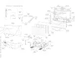
Page 23: ...Display The Main Cabinet Exploded View ...
Page 34: ......
Page 35: ......
Page 36: ......
Page 37: ...IIC BUS SIGNAL DIAGRAM ...
Page 39: ......
Page 40: ......
Page 41: ......
Page 42: ......
Page 43: ......
Page 44: ......
Page 45: ......
Page 46: ......
Page 47: ......
Page 48: ......
Page 49: ......
Page 50: ......
Page 51: ......
Page 52: ......
Page 53: ......
Page 54: ......
Page 55: ......
Page 56: ......
Page 57: ......
Page 58: ......
Page 59: ......
Page 60: ......
Page 61: ......
Page 62: ......
Page 63: ......
Page 64: ......
Page 65: ......
Page 66: ......
Page 67: ......
Page 68: ......
Page 69: ......
Page 70: ......
Page 71: ......
Page 72: ......
Page 73: ......
Page 74: ......
Page 75: ......
Page 76: ......
Page 77: ......
Page 78: ......
Page 79: ......
Page 80: ......
Page 81: ......
Page 82: ......
Page 83: ......
Page 84: ......
Page 87: ... W INPUT POWER PANEL Bottom View Return to Circuit Board TOC ...
Page 89: ... U1 MAIN POWER PANEL Bottom View Return to Circuit Board TOC ...
Page 91: ... K SYSTEM BOARD Bottom View Return to Circuit Board TOC ...
Page 92: ...Refer to the next page for Bottom Side View B SSB PANEL Top View Return to Circuit Board TOC ...
Page 93: ... B SSB PANEL Bottom View Return to Circuit Board TOC ...
Page 95: ... SL SCALER PANEL Bottom View Return to Circuit Board TOC ...
Page 97: ... F DW PIP PANEL Bottom View Return to Circuit Board TOC ...
Page 99: ... CB1 3D COMB FILTER PANEL Bottom View Return to Circuit Board TOC ...
Page 101: ... V REAR JACK PANEL Bottom View Return to Circuit Board TOC ...
Page 103: ... O1 SIDE JACK PANEL Bottom View Return to Circuit Board TOC ...
Page 105: ... LS LED SENSOR PANEL Bottom View Return to Circuit Board TOC ...
Page 107: ... P1 LED KEYBOARD PANEL Bottom View Return to Circuit Board TOC ...
Page 109: ... TS1 THERMAL SENSOR PANEL Bottom View Return to Circuit Board TOC ...
Page 111: ... AA1 AUDIO AMPLIFIER PANEL Bottom View Return to Circuit Board TOC ...
Page 112: ...Refer to the next page for Bottom Side View Return to Circuit Board TOC ...
Page 113: ...Return to Circuit Board TOC ...
Page 115: ... 7665 Page 1 P1 P2 P3 P4 P5 P6 P7 C1 C2 C3 C4 C5 C6 F30 F31 F32 L14 L15 L16 V31 ...
Page 116: ... 7665 Page 2 V32 F14 I 6 L 8 V 1 V 2 V 6 V 7 V 8 V 9 V10 L1 L2 L3 L4 L5 L6 L7 L8 L9 ...
Page 117: ... 7665 Page 3 F17 F18 F19 F20 L12 V19 V20 V21 V28 V29 V30 B51 B52 B53 B54 B55 B57 B58 B60 A15 ...
Page 121: ... 7665 Page 7 F2 F14 F15 F16 F17 F18 V19A V20A F 3 F 4 F 5 F 6 F 7 F 8 F 9 F10 F11 F12 F13 A1 ...
Page 122: ... 7665 Page 8 A2 A3 A4 A5 A6 A7 A8 ...
Page 124: ...Overall Cabinet Exploded View Page 1 of 5 ...
Page 125: ...Cabinet Detail 1 Exploded View Page 2 of 5 ...
Page 126: ...Cabinet Detail 2 Exploded View Page 3 of 5 ...
Page 127: ...Power Supply Assembly Exploded View Page 4 of 5 ...

