“Errors”
level shows
“No Errors.”
6
Alignments:
Allows access to 6 alignment menus.
General, Luminance Delay, MSB,
GDE-Video, GDE-NVM, and Gamma.
7
Dealer Options:
Allows access to dealer
“Personal Options”
menu.
8
Service Options:
Allows access to 6 service option menus. Dual Screen, Video repro,
Source Select, Audio repro, Miscellaneous, Opt. No.
9
Initialize NVM:
Not Accessible
10 Store Options:
Select “OK” to SAVE previously changed selections.
11 Functional Test:
This test finds module Errors and places the Error code in the “Errors”
register and shows the module name at the “Defective Module” level.
If this test finds no
faults, the ERROR buffer is set to “No Errors” and the “Defective Module” level shows
“NONE.”
SAM Menu Control
Menu items may be selected using the cursor UP/DOWN keys.
•
the selected option will be indicated by the enlarged bullet with red curser indicators
•
when not all menu options will fit on the screen, pressing the cursor UP/DOWN or LEFT/RIGHT keys,
on the remote transmitter, will display the next/previous menu.
With the cursor LEFT/RIGHT keys, it is possible to:
•
activate/deactivate the selected menu (e.g. ALIGNMENTS/GENERAL)
•
change the value of the selected menu item (e.g. TUNER AGC)
•
activate the selected submenu (e.g. TEST PATTERN)
Menu and Sub-menu Definitions
Reset Error Buffer
Erases the contents of the error buffer. Select the
“Reset Error Buffer”
menu item and press the
“OK” button or cursor the RIGHT cursor. The contents of the error buffer are cleared.
Error Code Buffer and Error Codes
Explanation of the Error code buffer
The error code buffer con tains all errors detected since the last time the buffer was erased. The buffer
is written from left to right. When an error occurs that is not yet in the error code buffer, the error code
will appear at the left side and all other errors shift one position to the right.
The error code buffer will be cleared in the following cases:
•
by activating “Reset Error Buffer” in SAM menu
•
upon automatic reset when content has not changed for 50 consecutive hours
By leaving SDM or SAM via the power switch, the error buffer will not be reset.
Examples:
ERROR: 000 000 000 : No errors detected
ERROR: 036 000 000 : Error code 036 is the last and only detec ted error
ERROR: 018 036 000 : Error code 036 was first detected and error code 018 is
the last detected (newest) error
The contents of the error buffer can also be displayed by use of the “blinking LED” procedure, if no
picture is available. See explanation of “The blinking LED procedure “below.
Summary of Contents for 55PL9524/37
Page 10: ...Page 9 of 15 2004 08 09 ...
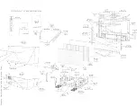
Page 23: ...Display The Main Cabinet Exploded View ...
Page 34: ......
Page 35: ......
Page 36: ......
Page 37: ...IIC BUS SIGNAL DIAGRAM ...
Page 39: ......
Page 40: ......
Page 41: ......
Page 42: ......
Page 43: ......
Page 44: ......
Page 45: ......
Page 46: ......
Page 47: ......
Page 48: ......
Page 49: ......
Page 50: ......
Page 51: ......
Page 52: ......
Page 53: ......
Page 54: ......
Page 55: ......
Page 56: ......
Page 57: ......
Page 58: ......
Page 59: ......
Page 60: ......
Page 61: ......
Page 62: ......
Page 63: ......
Page 64: ......
Page 65: ......
Page 66: ......
Page 67: ......
Page 68: ......
Page 69: ......
Page 70: ......
Page 71: ......
Page 72: ......
Page 73: ......
Page 74: ......
Page 75: ......
Page 76: ......
Page 77: ......
Page 78: ......
Page 79: ......
Page 80: ......
Page 81: ......
Page 82: ......
Page 83: ......
Page 84: ......
Page 87: ... W INPUT POWER PANEL Bottom View Return to Circuit Board TOC ...
Page 89: ... U1 MAIN POWER PANEL Bottom View Return to Circuit Board TOC ...
Page 91: ... K SYSTEM BOARD Bottom View Return to Circuit Board TOC ...
Page 92: ...Refer to the next page for Bottom Side View B SSB PANEL Top View Return to Circuit Board TOC ...
Page 93: ... B SSB PANEL Bottom View Return to Circuit Board TOC ...
Page 95: ... SL SCALER PANEL Bottom View Return to Circuit Board TOC ...
Page 97: ... F DW PIP PANEL Bottom View Return to Circuit Board TOC ...
Page 99: ... CB1 3D COMB FILTER PANEL Bottom View Return to Circuit Board TOC ...
Page 101: ... V REAR JACK PANEL Bottom View Return to Circuit Board TOC ...
Page 103: ... O1 SIDE JACK PANEL Bottom View Return to Circuit Board TOC ...
Page 105: ... LS LED SENSOR PANEL Bottom View Return to Circuit Board TOC ...
Page 107: ... P1 LED KEYBOARD PANEL Bottom View Return to Circuit Board TOC ...
Page 109: ... TS1 THERMAL SENSOR PANEL Bottom View Return to Circuit Board TOC ...
Page 111: ... AA1 AUDIO AMPLIFIER PANEL Bottom View Return to Circuit Board TOC ...
Page 112: ...Refer to the next page for Bottom Side View Return to Circuit Board TOC ...
Page 113: ...Return to Circuit Board TOC ...
Page 115: ... 7665 Page 1 P1 P2 P3 P4 P5 P6 P7 C1 C2 C3 C4 C5 C6 F30 F31 F32 L14 L15 L16 V31 ...
Page 116: ... 7665 Page 2 V32 F14 I 6 L 8 V 1 V 2 V 6 V 7 V 8 V 9 V10 L1 L2 L3 L4 L5 L6 L7 L8 L9 ...
Page 117: ... 7665 Page 3 F17 F18 F19 F20 L12 V19 V20 V21 V28 V29 V30 B51 B52 B53 B54 B55 B57 B58 B60 A15 ...
Page 121: ... 7665 Page 7 F2 F14 F15 F16 F17 F18 V19A V20A F 3 F 4 F 5 F 6 F 7 F 8 F 9 F10 F11 F12 F13 A1 ...
Page 122: ... 7665 Page 8 A2 A3 A4 A5 A6 A7 A8 ...
Page 124: ...Overall Cabinet Exploded View Page 1 of 5 ...
Page 125: ...Cabinet Detail 1 Exploded View Page 2 of 5 ...
Page 126: ...Cabinet Detail 2 Exploded View Page 3 of 5 ...
Page 127: ...Power Supply Assembly Exploded View Page 4 of 5 ...

