CLASS 1
LASER PRODUCT
GB
3140 785 22580
Published by SS 0115 Service Audio
or otherwise without the prior permission of Philips.
system or transmitted, in any form or by any means, electronic, mechanical, photocopying,
All rights reserved. No part of this publication may be reproduced, stored in a retrieval
Copyright 1995 Philips Consumer Electroncis B.V. Eindhoven, The Netherlands
be used.
condition and that parts which are identical with those specified
Safety regulations require that the set be restored to its original
C
PCS 107 271
Printed in The Netherlands
Copyright reserved
Subject to modification
CD Stereo Radio Recorder
TABLE OF CONTENTS
chapter
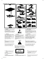
Handling chip components and safety
1 - 1
AZ2030
AZ2035
.............................
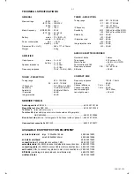
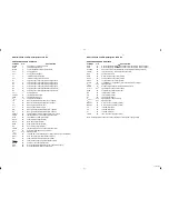
Technical Specification & Service Tools
2 - 1
..........................
Service Measurement
2 - 2
..................................................
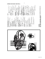
Connections & Controls
3 - 1
................................................
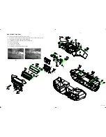
Disassembly Diagram
4 - 1
...................................................
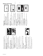
Instructions for use
3 - 2 to 3 - 6
.................................................
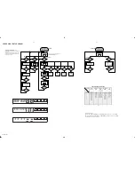
CD Service Test Program
4 - 2 to 4 - 3
........................................
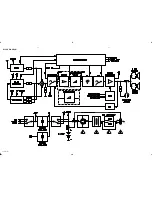
Block Diagram
5 - 1
.............................................................
Wiring Diagram
5 - 2
...........................................................
circuit diagram
6 - 1
.......................................................
FRONT BOARD
layout diagram
6 - 2
.......................................................
circuit diagram
7 - 1
.......................................................
AF & POWER BOARD
layout diagram
7 - 2
.......................................................
chapter
circuit diagram
8 - 1
.......................................................
FEATURE BOARD
layout diagram
8 - 1
.......................................................
circuit diagram
9 - 1
.......................................................
TUNER BOARD
layout diagram
9 - 2
.......................................................
circuit diagram
10 - 1
.......................................................
REOCRDER BOARD
layout diagram
10 - 2
.......................................................
circuit diagram
11 - 2
.......................................................
CD MODULE
layout diagram
11 - 1
.......................................................
cabinet
12 - 1
.................................................................
EXPLODED VIEWS DIAGRAM
tape deck
12 - 2
............................................................
Mechanical partslist
12 - 2
.....................................................
Electrical partslist
13 - 1 to 13 - 5
...............................................
all versions
Summary of Contents for AZ-2030
Page 4: ......
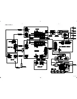
Page 14: ...BLOCK DIAGRAM 5 1 5 1 PCS 107 281 For AZ2035 only For AZ2030 only ...
Page 15: ...WIRING DIAGRAM 5 2 5 2 PCS 107 282 ...
Page 16: ...FRONT BOARD CIRCUIT DIAGRAM 6 1 6 1 PCS 107 283 ...
Page 17: ...FRONT BOARD LAYOUT DIAGRAM 6 2 6 2 PCS 107 284 ...
Page 18: ...AF POWER BOARD CIRCUIT DIAGRAM 7 1 7 1 PCS 107 285 ...
Page 20: ...FEATURE BOARD CIRCUIT DIAGRAM 8 1 8 1 PCS 107 287 ...
Page 21: ...FEATURE BOARD LAYOUT DIAGRAM 8 2 8 2 PCS 107 288 ...


