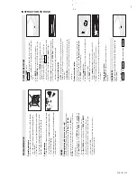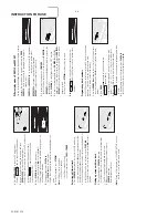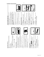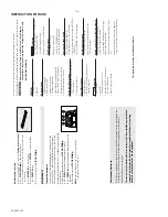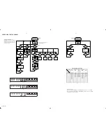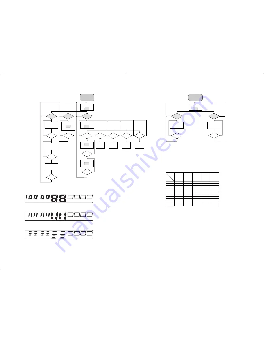
CD SERVICE TEST PROGRAM
4-2
4-2
PCS 107 280
STOP button pressed in any step returns
to begin of Service Testprogram.
NEXT button
pressed?
NEXT button
pressed?
N
Y
Y
Display shows all
segments and flags.
see figure 1
NEXt button
pressed?
N
Y
Y
Display shows all
segments and flags.
see figure 2
DISPLAY TEST
CD SERVO TEST
Display shows
version number
of the µP - software.
PLAY button
pressed?
Display shows
PLAY button
pressed?
NEXT button
pressed?
PREV. button
pressed?
PROG. button
pressed?
MODE button
pressed?
Slide moves
outside as long as
button is held
depressed.
Slide moves
inside as long as
button is held
depressed.
Y
Y
Y
Y
Y
N
N
N
N
N
FOCUS found?
Y
N
Display shows
objective moves up&down
disc motor for 160ms "on"
STOP button
pressed?
Y
N
Display shows
disc motor turns.
FOCUS search
SLIDE test
DISC MOTOR test
To enter Service
Testprogramm hold
PLAY & MODE buttons
depressed while switching
CD mode on.
fig. 1
*
*
*
To leave Service Testprogram switch mode switch
to off-position.
Door switch is ignored
Æ
CD door can be opened.
Slide servo, Radial servo, Focus servo, Disc motor
and Laser are switched off.
Mute is switched on via decoder IC.
* Volume up/down buttons function independentely
of the service testprogram.
N
N
NEXT button
pressed?
STOP button
pressed?
N
Y
Y
Display shows all
segments and flags.
see figure 1
DISPLAY TEST
Display shows
version number
of the µP - software.
To enter Service
Testprogramm hold
PLAY & MODE buttons
depressed while switching
TUNER mode on.
N
Y
table 1
N
PROG button
(Tuner)
pressed?
Service preset frequencies
acc. table 1 are copied
to the RAM.
Tuner is normal working
except the PROGRAM key.
STOP button
pressed?
N
Y
TUNER TEST
SERVICE PRESET FREQUENCIES
1)
How to set frequency grid:
AM - 9 kHz / FM - 50 kHz : Hold MODE KEY with the TUNING UP KEY simultaneously and then switch to TUNER.
AM - 10 kHz / FM - 100 kHz : Hold MODE KEY with the PROGRAM KEY simultaneously and then swutch to TUNER.
Selected frequency grid is stored in the EEPROM.
CD TEST
TUNER TEST
Disc motor turns
clockwise
as long as button
is held depressed.
(accelerate)
Disc motor turns
counter clockwise
as long as button
is held depressed.
(brake)
FOC-2
1
19
PREV button
pressed?
Y
N
Display shows
EP19
E2prom clear
STOP button
pressed?
N
Y
EP2PROM CLEAR
FOC 2
REGION
EUROPE
EUROPE2B
OVERSEAS
EAST-EUROPE
USA
FM/MW/LW
FM/MW
FM/MW
FM/MW
FM/MW
1)
Grid switchable
10-100kHz/9-50kHz
PRESET
/00/05/20/25
/00
/01/21
/14
/14/17/37
1
87.5 MHz
87.5 MHz
87.5 MHz
65.81 MHz
87.5 MHz
2
108 MHz
108 MHz
108 MHz
108 Mhz
108 MHz
3
531 kHz
531 kHz
531/530 KHz
74 MHz
530 kHz
4
1602 kHz
1602 kHz
1602/1700 kHz
87.5 MHz
1700 kHz
5
558 kHz
558 kHz
558/560 kHz
531 kHz
560 kHz
6
1494 kHz
1494 kHz
1494/1500 kHz
1602 kHz
1500 kHz
7
153 kHz
-
-
558 kHz
-
8
279 kHz
-
-
1494 kHz
-
9
198 kHz
-
-
-
-
10
-
-
-
-
-
11
-
-
-
-
-
12
-
-
-
-
-
13
-
-
-
-
-
19
STOP button
pressed?
N
Y
Display shows all
segments and flags.
see figure 3
fig. 2
fig. 3
PROGRAM
SHUFFLE
STEREO
REPEAT ALL
FM
LW
AM MW
Summary of Contents for AZ-2030
Page 4: ......
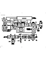
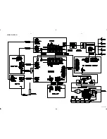
Page 14: ...BLOCK DIAGRAM 5 1 5 1 PCS 107 281 For AZ2035 only For AZ2030 only ...
Page 15: ...WIRING DIAGRAM 5 2 5 2 PCS 107 282 ...
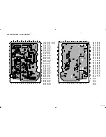
Page 16: ...FRONT BOARD CIRCUIT DIAGRAM 6 1 6 1 PCS 107 283 ...
Page 17: ...FRONT BOARD LAYOUT DIAGRAM 6 2 6 2 PCS 107 284 ...
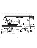
Page 18: ...AF POWER BOARD CIRCUIT DIAGRAM 7 1 7 1 PCS 107 285 ...
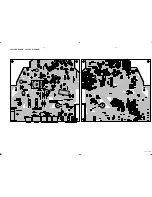
Page 20: ...FEATURE BOARD CIRCUIT DIAGRAM 8 1 8 1 PCS 107 287 ...
Page 21: ...FEATURE BOARD LAYOUT DIAGRAM 8 2 8 2 PCS 107 288 ...


