background image

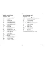
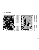
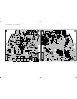
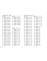
AF & POWER BOARD - LAYOUT DIAGRAM

7-2

7-2

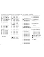
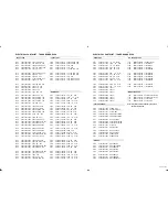
PCS 107 286

300 F6

3333 H5

9227 B6

301 D3

3337 H5

9228 A5

1300 E2

3339 H5

9229 E6

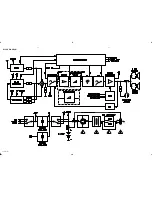
1301 C1

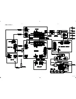
3352 H5

1302 A5

3353 I4

1303 A4

3354 G5

1304 B2

3359 D4

1305 H2

5300 B5

1306 I1

5301 D5

1307 A2

5302 D5

1308 G2

5303 E6

1310 D2

6300 F1

1311 B1

6312 E4

2300 A6

6313 F4

2301 E2

6314 G3

2302 E2

6315 G3

2303 D2

7300 F4

2304 E2

7301 G4

2306 E4

7302 F4

2307 E4

7305 C6

2308 D4

7306 G6

2309 C5

7307 H6

2311 C5

7308 I6

2313 D5

7309 I6

2314 C4

7312 I7

2315 E5

7316 I5

2316 A2

7317 I5

2317 B3

7318 G6

2318 H4

9201 A3

2319 H3

9202 B4

2321 B6

9203 C3

2322 B2

9204 B4

2323 A1

9205 C3

2324 F5

9206 C4

2326 B5

9207 I4

2331 E2

9208 A4

2338 F4

9209 B4

3301 G4

9211 E4

3302 G4

9212 B4

3303 G4

9213 C4

3304 E4

9219 G5

3318 G5

9222 I2

3321 H5

9223 H2

3325 I5

9224 D6

3330 F5

9225 D6

3331 F5

9226 C6

2310 D2

3344 G2

7303 G4

2312 D2

3345 B3

7304 F4

2320 A6

3346 I5

7310 G2

2325 A7

3347 I5

7311 G3

2329 H6

3348 C3

7313 H2

2330 H6

3349 F3

7314 G2

2332 F2

3350 I6

7315 H4

2333 A6

3351 H6

7319 F2

2334 A6

3355 H6

7320 D5

2335 F3

3356 H6

2336 F3

3357 C6

2337 F3

3358 C6

3305 G4

3360 E2

3306 E3

3361 F2

3307 G5

3362 F2

3308 G5

3363 E5

3309 F5

3364 E5

3310 F5

4201 F5

3311 D3

4202 F5

3312 C2

4203 A4

3313 C3

4205 F3

3314 D3

4206 F2

3316 C2

4209 E3

3317 C3

4210 F2

3319 D3

4211 E3

3322 D3

4300 C3

3326 D3

4301 C3

3327 D5

4302 D4

3328 D3

4303 E3

3329 D3

4304 E2

3334 G3

4310 E5

3335 G5

4311 E5

3336 E2

4312 F5

3338 E2

6316 B3

3341 I5

6317 E2

3342 I4

6318 F2

3343 H2

6319 E5

Summary of Contents for AZ-2030

Page 1: ...to modification CD Stereo Radio Recorder TABLE OF CONTENTS chapter Handling chip components and safety 1 1 AZ2030 AZ2035 Technical Specification Service Tools 2 1 Service Measurement 2 2 Connections Controls 3 1 Disassembly Diagram 4 1 Instructions for use 3 2 to 3 6 CD Service Test Program 4 2 to 4 3 Block Diagram 5 1 Wiring Diagram 5 2 circuit diagram 6 1 FRONT BOARD layout diagram 6 2 circuit d...

Page 2: ... essere collegato allo stesso potenziale che quello della massa delápparecchio tramite un braccialetto a resistenza Assicurarsi che i componenti e anche gli utensili con quali si lavora siano anche a questo potenziale Safety regulations require that the set be restored to its original condition and that parts which are identical with those specified be used Safety components are marked by the symb...

Page 3: ... 14 230 V 01 11 16 120 230 V 05 10 240 V 17 120 V Mains frequency 00 05 10 14 50 Hz 01 11 16 50 60 Hz 17 60 Hz Battery mains 12 V R20 x 8 remote 3 V R03 x 2 Power consumption max 35 W standby 2 3 W Dimension W x H x D 540 x 177 x 276 mm Weight 5 5 kg AMPLIFIER Output power mains 2 x 6 W battery 2 x 6 W Speaker impedance 2 x 8 Ohm 2 x Frequency response 70 Hz 10 kHz 3dB TUNER FM SECTION Tuning rang...

Page 4: ......

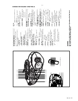
Page 5: ...ND selects waveband PRESET 4 3 selects a preset tuner station down up REMOTE SENSOR for AZ2035 model only infrared sensor for remote control BACK PANEL Telescopic aerial improves FM reception AC MAINS inlet for mains lead Voltage selector on the back of the set some versions only before plugging in the set adjust selector to match the local voltage Battery compartment for eight batteries type R 20...

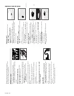
Page 6: ...supply 3 Connect the mains lead to the wall socket and the set is now ready for use 4 To disconnect the set from the mains supply completely remove the mains plug from the wall socket 8 x R20 UM 1 D CELLS MAINS Switching on and off Adjust the POWER slider to the desired sound source CD TUNER or TAPE During playback the PLAY 2 STOP 9 and PRESET 4 3 keys on the set light up The set is switched off w...

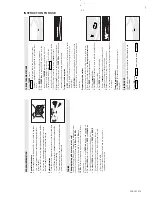
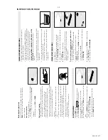
Page 7: ...ning to preset stations Press PRESET 4 or 3 until the desired preset station is displayed PLAYING A CD This CD player plays Audio Discs including CD Recordables and CD Rewritables 1 Select CD source and are displayed briefly if PL AY ST OP CD MO DE SE AR CH SE AR CH PR OG BA ND PR ES ET FM FM ST ER EO ST ER EO BAT T LOW BATT LOW P R O G R A M S T E R E O F M BATT LOW A M INSTRUCTION FOR USE GENERA...

Page 8: ... MO DE SE AR CH SE AR CH SE AR CH PR OG BA ND PR E PR ES E BAT T TT LOW BATT LOW S H U F F L E R E P E A T A L L INSTRUCTION FOR USE 2 Press OPEN CLOSE to open the CD compartment Display when you open the CD compartment 3 Insert a CD with the printed side facing up and press OPEN CLOSE to close the CD compartment Display the CD player scans the contents of a CD and then the total number of tracks ...

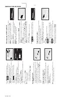
Page 9: ... AR CH SE AR CH SE AR CH PR OG BA ND FM ST ER EO BAT T LOW FM B A Reviewing the programme In the STOP position or during playback press and hold down PROG for a while until the display shows all your stored track numbers in sequence Erasing a programme You can erase the programme by pressing STOP 9 twice in the STOP position or during playback scrolls across the display briefly and PROGRAM disappe...

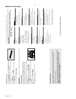
Page 10: ...oes not function properly Batteries dead incorrectly inserted Insert fresh batteries correctly Distance angle between the set too large Reduce the distance angle Remote sensor obstructed by object sticker etc Remove obstruction make sure right hand side of cassette door is free from obstruction The type plate is located on the bottom of the set Recording from the radio 1 Tune to the desired radio ...

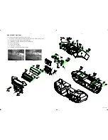
Page 11: ... the centre back ventilation slot to remove Top Cabinet see fig 1 2 B To separate Top Cabinet and Top Cabinet Bracket C To separate Front Panel Assy and Top Cabinet Bracket D To reomve Tape Deck E To remove Front Board F To remove Panel LCD Assy G To separate Front Cabinet and Rear Cabinet fig 1 fig 2 ...

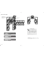
Page 12: ...version number of the µP software To enter Service Testprogramm hold PLAY MODE buttons depressed while switching TUNER mode on N Y table 1 N PROG button Tuner pressed Service preset frequencies acc table 1 are copied to the RAM Tuner is normal working except the PROGRAM key STOP button pressed N Y TUNER TEST SERVICE PRESET FREQUENCIES 1 How to set frequency grid AM 9 kHz FM 50 kHz Hold MODE KEY wi...

Page 13: ...utput programmable open drain VSSD1 33 1 digital ground 2 V2 V3 34 versatile I O input versatile pin 2 or output versatile pin 3 open drain WCLI 35 word clock iutput for data loopback to DAC SDI 36 serial data input for data loopback to DAC SCLI 37 serial bit clock input for data loopback to DAC RESET 38 power on reset input active LOW SDA 39 microcontroller interface data I O line open drain outp...

Page 14: ...BLOCK DIAGRAM 5 1 5 1 PCS 107 281 For AZ2035 only For AZ2030 only ...

Page 15: ...WIRING DIAGRAM 5 2 5 2 PCS 107 282 ...

Page 16: ...FRONT BOARD CIRCUIT DIAGRAM 6 1 6 1 PCS 107 283 ...

Page 17: ...FRONT BOARD LAYOUT DIAGRAM 6 2 6 2 PCS 107 284 ...

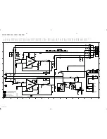
Page 18: ...AF POWER BOARD CIRCUIT DIAGRAM 7 1 7 1 PCS 107 285 ...

Page 19: ...1 E2 9208 A4 2338 F4 9209 B4 3301 G4 9211 E4 3302 G4 9212 B4 3303 G4 9213 C4 3304 E4 9219 G5 3318 G5 9222 I2 3321 H5 9223 H2 3325 I5 9224 D6 3330 F5 9225 D6 3331 F5 9226 C6 2310 D2 3344 G2 7303 G4 2312 D2 3345 B3 7304 F4 2320 A6 3346 I5 7310 G2 2325 A7 3347 I5 7311 G3 2329 H6 3348 C3 7313 H2 2330 H6 3349 F3 7314 G2 2332 F2 3350 I6 7315 H4 2333 A6 3351 H6 7319 F2 2334 A6 3355 H6 7320 D5 2335 F3 335...

Page 20: ...FEATURE BOARD CIRCUIT DIAGRAM 8 1 8 1 PCS 107 287 ...

Page 21: ...FEATURE BOARD LAYOUT DIAGRAM 8 2 8 2 PCS 107 288 ...

Page 22: ...0kHz 14 FM OIRT MW MPX AM AFC AM FRAME AERIAL Printed 1 2 3 4 5 6 7 8 9 10 11 12 13 14 VCO 00 02 FM MW LW 6120 1 2 3 4 5 6 7 8 9 to from MW FM IF2 VOLTAGE MULTIPLIER Ferrite Antenna only AM RF STEREO 10 11 12 13 14 A B C D E F G H I A B C D 3170 01 FM MW Printed LW HIGH VERSION DETECTION LEFT AM OSCILLATOR FM AM IF2 TUNER BOARD ECO6 PORTABLE AUDIO RIGHT Printed VERSION 00 02 FM MW LW HIGH 5104 fro...

Page 23: ...7109 E5 7111 A5 7122 B2 7124 C2 7180 B7 7181 C7 7182 D7 7183 B7 TUNER BOARD ECO6 PA copperside view VARICAP ALIGNMENT FM RF FM IF VCO AM IF AM RF 3 108MHz 87 5MHz 65 81MHz 87 5MHz 65 81MHz 87 5MHz 65 81MHz 279kHz 153kHz 1602kHz 531kHz 5130 check 5122 check 5123 check 8V 0 2V 4 3V 0 5V 1 2V 0 5V 8V 0 2V 1 1V 0 4V 8V 0 2V 1 1V 0 4V 1494kHz 558kHz 560kHz 1500kHz 5105 LW ferrite coil 198kHz 1494kHz 55...

Page 24: ...ACITOR ALL TUBULAR CERAMIC CAPACITORS UNLESS OTHERWISE STATED ALL CARBON RESISTORS E12 SERIES G 50V f 25V 0 33W 5 UNLESS OTHERWISE STATED o 1 2 3 4 5 6 9 8 7 10 11 12 13 14 15 18 17 16 PLAY RECORD 1707 RECORD PLAY V 5V 5V1 0V 0V 1V5 1V7 2V6 4V2 1V5 0V 0V 2V6 0V REC INFO REC L OPT OPT OPT OPT OPTIONAL Used for some Versions d 10V E 16V OPT 1725 FE 1 2 3 4 5 6 2728 4n7 2729 4n7 2738 10n 2739 10n 275...

Page 25: ... 3 2719 A 3 2720 C 3 2721 C 4 2722 C 2 2723 C 2 2726 C 2 2727 D 2 2728 C 5 2729 C 5 2730 D 1 2731 C 1 2732 B 1 2733 C 1 2734 A 1 2735 A 1 2738 D 4 2739 C 4 2740 C 4 2750 B 3 2751 C 2 2760 A 2 3701 A 2 3703 B 4 3704 B 4 3706 B 3 3707 B 2 3710 A 3 3711 C 3 3712 D 1 3713 C 3 3714 C 4 3716 C 3 3719 C 2 3720 D 2 3721 D 3 3722 D 5 3723 C 5 3724 A 5 3726 A 3 3727 A 3 3728 A 4 3730 B 1 3731 B 1 3732 B 1 3...

Page 26: ... 3883 F3 3884 E3 3885 B5 3886 C5 3887 B5 3888 C5 3889 D5 3890 D2 3891 E2 3892 D2 3893 D2 3894 E3 3895 E2 3896 E2 3897 D2 3898 D2 3899 D2 3900 D4 4801 E5 4802 F2 4804 D4 4805 E4 4806 D5 4807 E2 4808 D5 4809 D5 4810 B2 4812 B4 4813 B3 4814 B3 4815 A4 4823 C2 4824 B2 4828 B2 4831 B3 4832 B3 4838 C5 4845 D2 4847 E1 4848 B4 4850 G5 4853 F2 4856 F5 4857 B4 4859 B5 4863 C5 4865 A4 4866 B4 4872 F2 4877 H5...

Page 27: ...803 82p 470R 15K 3843 1K 100K 3892 3816 47K 3859 3893 100K 2818 47n 2822 1n5 2826 47n 7802 A A 1 Y 2 82p 2805 33R 3827 3745 10R 2831 1u 3829 100R 3 3V 10K 3896 470R 22K 3831 3839 4K7 3841 3803 27K 47K 3861 3 3V 2819 33p LDON 2806 82p drive_recognition 3K9 3858 180p 2865 47u 2840 22K 3834 5V 180p 3807 1K5 2864 3890 100K 3815 4K7 3856 68K 3860 1K 100K 3891 3862 1K 3728 47R 3servo 3801 150K 7807 BC84...

Page 28: ...ng 5mm A F Hexgonal Type 3 C2 x 8 4 C2 5 x 10 5 C3 x 8 6 C3 x 10 7 C3 x 12 8 C3 x 16 9 C3 x 20 10 C3 x 25 11 C3 x 34 12 P W C2 5 x 10 13 P W C3 x 10 14 P W C3 x 16 469 SHUFFLE REPEAT TUNING PRESET SEARCH SEARCH STOP VOLUME Digital Remote Control 468 401 402 403 404 406 407 408 409 501 432 433 431 434 436 437 506 439 507 441 442 443 444 446 447 448 449 451 452 454 438 456 457 458 462 461 509 511 51...

Page 29: ...DOOR COVER 417 9965 000 08539 DISPLAY LENS 457 9965 000 08532 HANDLE BRACKET 418 9965 000 08492 BRACKET BACKLIGHT 458 9965 000 08537 HANDLE TOP 419 9965 000 08491 LENS BACKLIGHT 459 9965 000 08538 HANDLE BOTTOM 421 4822 691 10612 TAPE DECK MECHANISM 461 9965 000 08534 SPK CLOTH FRAME L 422 9965 000 08506 REC SPRING 462 9965 000 08535 SPK CLOTH FRAME R FOR AZ2030 423 9965 000 08494 CASS KNOB PAUSE ...

Page 30: ...9 60177 IC LM339D Q601 4822 130 60511 TRANS BC847B Q602 4822 130 60511 TRANS BC847B Q603 4822 130 60511 TRANS BC847B Q604 9965 000 04928 TRANS ON4986 Q605 9965 000 04928 TRANS ON4986 Q606 9965 000 04928 TRANS ON4986 Q607 9965 000 04928 TRANS ON4986 Q608 4822 130 60511 TRANS BC847B Q609 4822 130 60511 TRANS BC847B Q610 4822 130 60511 TRANS BC847B Q611 4822 130 60511 TRANS BC847B Q612 4822 130 60511...

Page 31: ...471 470R 5 0 1W 2159 5322 122 32659 33pF 5 50V 3159 4822 051 20471 470R 5 0 1W 2163 4822 126 13838 100nF 80 20 Y5V 50V 3160 4822 051 20471 470R 5 0 1W 2164 4822 126 13482 470nF 80 20 16V 3161 4822 051 20223 22K 5 0 1W 2165 4822 126 13838 100nF 80 20 Y5V 50V 3166 4822 051 20479 47R 5 0 1W 2166 5322 122 31647 1nF 10 X7R 63V 3167 4822 051 20479 47R 5 0 1W 2167 4822 122 33926 12pF 50V 3169 4822 051 20...

Page 32: ...2233575 220pF 5 NP0 63V 3822 482205120332 3K3 5 0 1W 2851 482212440248 10µF 20 63V 3823 482205120332 3K3 5 0 1W 2853 482212233177 10nF 20 X7R 50V 3824 482205110102 1K 2 0 25W 2854 482212411912 220µF 20 6 3V 3825 482205120223 22K 5 0 1W ELECTRICAL PARTSLIST CD99 DA11 RESISTORS RESISTORS 3826 482205120273 27K 5 0 1W 3883 482205110102 1K 2 0 25W 3827 482205120339 33R 5 0 1W 3884 482205110102 1K 2 0 2...

Page 33: ...SAA7325H 7802 532220911517 IC PC74HCU04T 7803 532213060123 Trans BC807 40 7804 532220982941 IC LM358D 7807 532213042755 Trans BC847C 7808 482220932852 IC TDA7073A N2 7809 482220932852 IC TDA7073A N2 7810 482220933165 IC TDA1308T N1 7875 482213060511 Trans BC847B MISCELLANEOUS 1800 482226510925 Connector 15P 1823 482226511207 Connector 6P 1824 482226511207 Connector 6P 8000 482232012178 Flexible Fo...

Page 34: ...6V COIL 2723 482212612882 100nF 80 20 50V 5701 482215710371 Coil 100kHz 2726 482212613098 5 6nF 20 16V 2727 482212612878 1 5nF 10 16V DIODE 2728 482212611714 4 7nF 20 2729 482212611714 4 7nF 20 6704 482213030621 Diode 1N4148 2730 202030090561 1 2nF 10 IC TRANSISTORS 2732 482212210577 3 3nF 10 16V 2733 482212151387 10nF 20 16V 7702 482213040981 Trans BC337 25 2738 482212151387 10nF 20 16V 7705 4822...

Reviews: