1 2
3
4
5 6 7 8
!
0
9
3 - 1
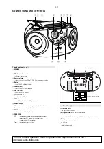
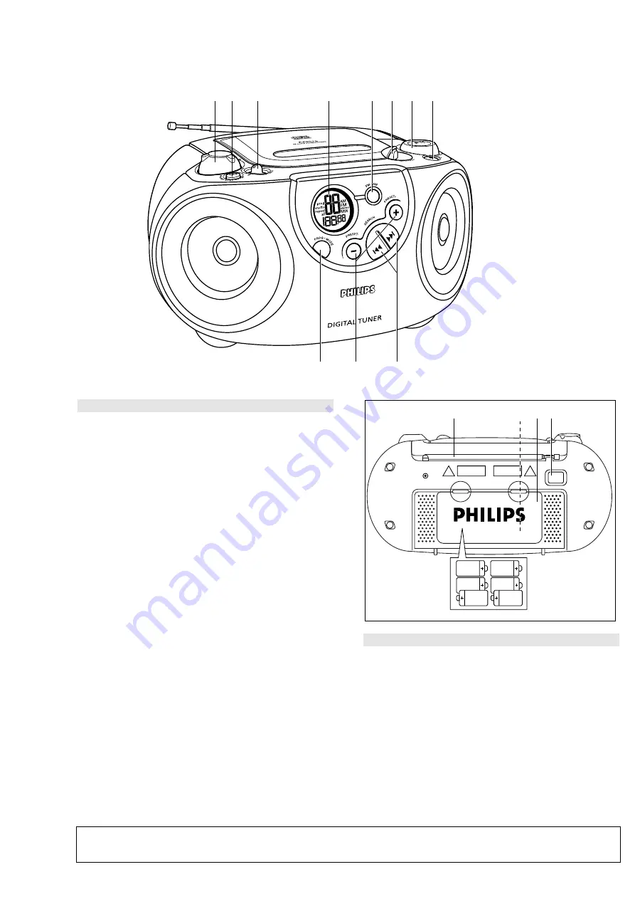
Top and front panels (See
1
)
1
VOLUME
– adjusts volume level
2
DBB
(Dynamic Bass Boost)
– enhances bass response
3
Source selector
– selects source of sound CD or TUNER. Also the power off switch
4
Display
– shows the CD and tuner functions
5
FM•MW (AM)
– selects FM/ MW (AM) waveband
6
LIFT TO OPEN
– opens/ closes the CD door
7
PRESS TO PLAY
2;
– starts or pauses CD play
8
STOP
9
– stops CD playback; erases a CD programme
9
SEARCH
∞
,
§
CD:
skips or searches a passage/track backwards or forward
Tuner:
tunes to a station (up, down)
0
,
–
– selects a preset station (up, down)
!
PROG MODE
CD:
– programmes and reviews programmed track numbers;
– plays tracks CD/ programme in random order;
– repeats a track/CD/ programme
Tuner:
– programmes preset stations
Back Panel (See
1
)
@
Telescopic aerial
– to improve FM reception
#
Voltage selector
(inside battery compartment,
some versions only)
– adjust to match the local voltage 110/220V before plugging in the set
$
Battery door
– to open battery compartment
%
AC MAINS
– inlet for mains lead
3 x 2 R14 • UM2 • C-CELLS
@
$
#
%
CONNECTIONS AND CONTROLS
For more detail on operation instruction please visit Philips Audio internet site :
http://www.audio.philips.com
Summary of Contents for AZ 3010 series
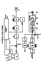
Page 6: ...4 1 ...
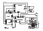
Page 7: ...4 2 4 2 VOLUME BD PLAY STOP BD CN205 CN606 CN604 CN607 CN206 CN105 CN106 CN303 WIRING DIAGRAM ...
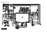
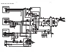
Page 8: ...5 1 5 1 FRONT BOARD CIRCUIT DIAGRAM ...
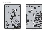
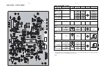
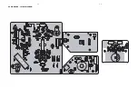
Page 9: ...5 2 5 2 FRONT BOARD LAYOUT DIAGRAM SOLDER SIDE COMPONENT SIDE ...
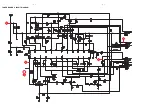
Page 10: ...6 1 6 1 B A 1 4 C TUNER BOARD CIRCUIT DIAGRAM ...
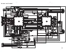
Page 12: ...7 1 7 1 CD BOARD CIRCUIT DIAGRAM ...
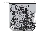
Page 13: ...7 2 7 2 CD BOARD LAYOUT DIAGRAM ...
Page 14: ...8 1 8 1 AUDIO BOARD CIRCUIT DIAGRAM ...


