background image

2-1

CS 46 432

SERVICE HINTS

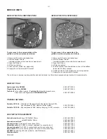
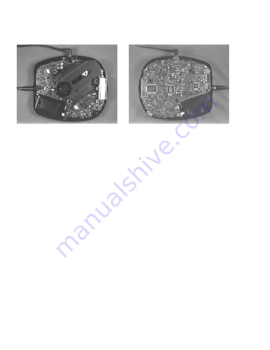
REPAIR POSITION COPPERSIDE

To get access to the componentside of the
printed circuit board proceed as follows:

1. Disconnect DC-cable and headphone
2. Remove bottom screws

(remember hidden screw in battery compartment)

3. Open the CD-door
4. Lift the top-cabinet
5. Close the door-switch (e.g. paper-clip)
6. Supply the unit via external DC-socket

To get access to the copperside of the
printed circuit board proceed as follows:

1. Disconnect DC-cable and headphone
2. Remove bottom screws

(remember hidden screw in battery compartment)

3. Open the CD-door
4. Lift the top-cabinet
5. Take the printed circuit board/drive unit out of the bottom

(take care of battery springs)

6. Position printed circuit board/drive unit into top-cabinet
7. Supply the unit via external DC-socket

SERVICE TOOLS

Audio signal disc SBC429

4822 397 30184

Playability test disc SBC444

4822 397 30245

Test disc 5 (disc without errors) + Test disc 5A (disc with dropout errors,

black spots and fingerprints) SBC426/SBC426A

4822 397 30096

TRAINING MATERIAL

Portable CD 1994 – Principles of Electronic Shock Absorption System ESA,

Key components 1994, Remote control system

4822 725 24941

Portable CD 1996 – Key components 1996, Battery charging, DC/DC-converter

4822 725 24986

ESD PROTECTION EQUIPMENT

Anti-static table mat large 1200x650x1.25mm

4822 466 10953

small 600x650x1.25mm

4822 466 10958

Anti-static wristband

4822 395 10223

Connection box (3 press stud connections, 1M

)

4822 320 11307

Extendible cable (2m, 2M

, to connect wristband to connection box)

4822 320 11305

Connecting cable (3m, 2M

, to connect table mat to connection box)

4822 320 11306

Earth cable (1M

, to connect any product to mat or to connection box)

4822 320 11308

KIT ESD3 (combining all 6 prior products - small table mat)

4822 310 10671

Wristband tester

4822 344 13999

REPAIR POSITION COMPONENTSIDE

The unit is now in a proper working position and can be turned in all directions necessary to get access for measurements.

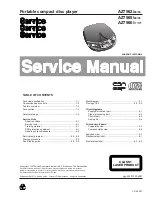
Summary of Contents for AZ 7566

Page 1: ...o part 4 4 Printed circuit board Copperside view 4 5 Componentside view 4 6 Exploded view 5 1 Mechanical partslist 5 1 Electrical partslist 6 1 6 3 CS 46 427 AZ7562 00 05 4822 725 26007 Published by PW 9713 Service Audio Printed in The Netherlands Subject to modification Portable compact disc player PLAY PA USE CLASS 1 LASER PRODUCT AZ7565 00 05 AZ7566 17 17T TABLE OF CONTENTS Copyright 1997 Phili...

Page 2: ... Optical output not on all versions Connection 3 5mm optical fiber jack Specification according to IEC958 Laser Output power 5mW 3mW typ Wavelength 780nm Measurement setup Use Audio Signal disc SBC429 4822 397 30184 L R LEVEL METER e g Sennheiser UPM550 with FF filter S N and distortion meter e g Sound Technology ST1700B N O I T A R E P O N O I T A R E P O N O I T A R E P O N O I T A R E P O N O I...

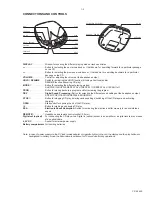
Page 3: ... off STOP 9 Button for stopping CD play deleting various settings switching off the CD player and activating charging OPEN Slide control for opening the lid of the CD player 2 Button for starting and pausing CD play ESA Electronic Shock Absorption Switch for activating the electronic buffer memory for an undisturbed sound REMOTE p Headphone and remote control socket 3 5mm Digital out optical For c...

Page 4: ...7 1 3 6 5 3 Y A 7 1 3 6 5 3 Y A 7 1 3 6 5 3 Y A E T A L P R O T P A D A R A C 1 0 1 1 2 3 6 2 2 2 8 4 O O 0 0 2 7 6 3 Y A 0 0 2 7 6 3 Y A 0 0 2 7 6 3 Y A 0 0 2 7 6 3 Y A 0 0 2 7 6 3 Y A E N O H P R A E 3 4 3 0 1 2 4 2 2 2 8 4 X X S 0 0 2 7 6 3 Y A S 0 0 2 7 6 3 Y A S 0 0 2 7 6 3 Y A S 0 0 2 7 6 3 Y A S 0 0 2 7 6 3 Y A E N O H P R A E 1 4 3 0 1 2 4 2 2 2 8 4 X X 7 3 1 8 6 3 Y A 7 3 1 8 6 3 Y A 7 3 ...

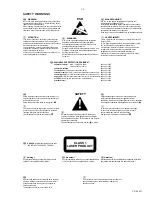
Page 5: ...parts which are identical with those specified be used Safety components are marked by the symbol i Le norme di sicurezza estigono che l apparecchio venga rimesso nelle condizioni originali e che siano utilizzati i pezzi di ricambiago identici a quelli specificati Componenty di sicurezza sono marcati con ñ Veiligheidsbepalingen vereisen dat het apparaat in zijn oorspronkeliijke toestand wordt teru...

Page 6: ...7 30245 Test disc 5 disc without errors Test disc 5A disc with dropout errors black spots and fingerprints SBC426 SBC426A 4822 397 30096 TRAINING MATERIAL Portable CD 1994 Principles of Electronic Shock Absorption System ESA Key components 1994 Remote control system 4822 725 24941 Portable CD 1996 Key components 1996 Battery charging DC DC converter 4822 725 24986 ESD PROTECTION EQUIPMENT Anti sta...

Page 7: ...2 2 CS 46 433 HANDLING CHIP COMPONENTS ...

Page 8: ...RVO TEST Purpose Check door and inner switch movement of slide and acceleration of discmotor To enter the servo test start service test program and press the PLAY button The display shows S xy x indicates state of door switch y indicates state of inner switch x y 1 means switch is open To move slide outside hold the NEXT button depressed To move slide inside hold the PREV button depressed To accel...

Page 9: ... Y N Y N Y N Y N Y CODE E 1001 E 1002 E 1003 E 1004 E 1005 E 1011 E 1012 E 1013 E 1014 E 1018 E 1019 ERROR sledge out error focus error radial error subcode error DRAM filling error sledge in error focus search error fatal radial error fatal subcode error motor N1 error motor N2 error TYPE non fatal non fatal non fatal non fatal non fatal fatal fatal fatal fatal fatal fatal CAUSE The sledge did no...

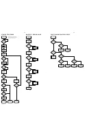
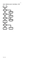
Page 10: ...N N N Y Y Y Y Y Y Y N POWER OFF stand by display shows no disc start up stopped display shows Error start up stopped PLAY MODE turntable and disc free N N Y lens movement Y CHECK LIGHTPATH CHECK FOCUS PATH N triangle voltage on focus actuator OK Y N connections to from CD drive OK Y replace CD drive repair connections triangle voltage on pin 42 of 7950 check servo driver 7950 N Y check CD7 7830 Y ...

Page 11: ...on pin 4 of 1800 1 2V voltage on pin 16 of 7800 1 8 2 0V Y check 2800 3800 N Y replace CD drive N photodiodes OK Y replace CD drive replace CD drive N Y N Y check CD7 7830 check supply 3 5 comp around 7901 OK N Y repair replace HF amplifier 7800 pin 8 of 7800 2 5V pin 7 of 7800 high FAULT FINDING GUIDE LIGHTPATH ...

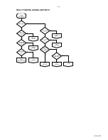
Page 12: ...N Y repair connections turntable and disc free mechanical obstruction Y N check servo driver 7950 check CD7 7830 check CD7 7830 focus OK eye pattern OK Y N Y Y CHECK LIGHTPATH N N Y N check servo driver 7950 replace CD drive PWM output on pin 33 of 7830 PWM output on pin 33 of 7830 servo signals on pin 2 44 of 7950 FAULT FINDING GUIDE TURNTABLE MOTOR PATH ...

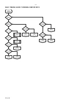
Page 13: ...rvo signals on pin 37 of 7950 check servo driver 7950 N Y check CD7 7830 CHECK LIGHTPATH tracking N Y N servo signals on track servo Y N connections to from CD drive OK Y replace CD drive repair connections servo signals on pin 36 of 7950 check servo driver 7950 N Y check CD7 7830 enter service program RADIAL TEST enter service program SERVO TEST check CD7 7830 FAULT FINDING GUIDE RADIAL TRACKING ...

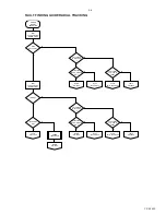
Page 14: ...truction N FUNCTIONAL TEST start over drive servo checks remove obstruction Y set sensitive to temperature N localize temperature sensitive part repair Y still errors during playback N replace set replace CD drive SET REPAIRED FAULT FINDING GUIDE FUNCTIONAL TEST ...

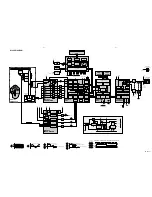
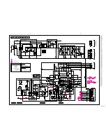
Page 15: ...signal SLIDE_IN FOCUS_IN DM Sldm Focus TRACK_IN H BRIDGE MOTOR DRIVER 3 H BRIDGE MOTOR DRIVER 1 H BRIDGE MOTOR DRIVER 4 H BRIDGE MOTOR DRIVER 2 DC DC CONVERTER FEED BACK S 1 2 Pow on A A CLsaw 1 8 MPC1718 SERVO DRIVER SAWTOOTH OSCILLATOR DM_IN MOTO1 FROM CD7 A CLsaw A CLsaw A CLsaw A CLsaw CLsaw 3 5 Power switch Reg Ref Track L P F L P F L P F L P F FLEX PCB HEADPHONE RC SOCKET RIGHT Vol Vor Vcom ...

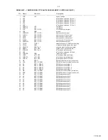
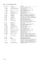
Page 16: ...D supply analog of CD7 2 VDDA1 3 5 supply analog of CD7 3 D1 HF preamp CD7 unipolar current input central diode signal input 4 D2 HF preamp CD7 unipolar current input central diode signal input 5 D3 HF preamp CD7 unipolar current input central diode signal input 6 VRL GND reference input for ADC 7 D4 HF preamp CD7 unipolar current input central diode signal input 8 R1 HF preamp CD7 unipolar curren...

Page 17: ...t 20 RESET µP NPC system reset input active low 21 ZSENSE NPC µP µP interface status output 22 UC6 µP interface extension I O line6 23 YDMUTE GND forced mute input 24 YMLD µP NPC µP interface latch clock input 25 YMDATA µP NPC µP interface serial data input 26 YMCLK µP NPC µP interface shift clock input 27 OE NPC DRAM OE control output active low 28 CAS NPC DRAM DRAM CAS control output active low ...

Page 18: ...hronized to the clock 23 Sync servo driver external clock input for separate excitation 24 Power µP servo driver power control pin low active 25 Hout3B servo driver track servo H bridge PWM output 3B 26 Hin3 servo driver power supply for H bridge output section 3 27 Hout3A servo driver track servo H bridge PWM output 3A 28 Gnd3 4 GND ground for H bridge section 3 and 4 29 DCout3 DC DC converter 3 ...

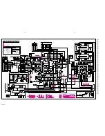
Page 19: ... 8k2 3295A 22k 3284 22k 3290 10k 3272A 100k 3270A 470k 3271A 10k 3273 100k 3274 100k 3275 22k 3278A 22k 3277A 100k 3276A 100k 3279A 33k 3296A 22k 3297 470k 3298 12k 3289 2k2 3935 0R05 2283 2n2 100n 2255 15n 2822 15n 2816 150n 2951 100n 2959 2960 100n 2930 100n 100n 2958 2924 22n 2922 100n 1n 2927 2920 100n 2925 100p 1u 2956 150n 2935 1n 2961 2931 1n 2280A 330p 2281 100n 2282 100n 2919 100n 2918 22...

Page 20: ...814 2818 3n3 22p 2841E 2842E 22p 2829 2n2 22n 2836 47p 2835 10n 2834 82p 2832X 2803 2804 2805 2806 2807 2808 100n 2827 2825 100n 100n 2850 2824 33n 33n 2855 100n 2826 4p7 2843 4p7 2844 DC_ON DC_ON 3 5 3 5 3 5 3 5 3 5 3 5 3 5 3 5 3 5 3 5 3 5 3 5 3 5 3 5 3 5 3 5 3 5 3 DC_ON INNERSW CL16 AMB_ON TREB YMCLK YMDATA YMLD ZSENSE STATUS SBSY SCL SDA PORES RA SILD DM_IN FOCUS_IN TRACK_IN SLIDE_IN DR_REF SRD...

Page 21: ...k 3452 100k 3451 2k2 3455 3M3 3456 3401 100 3402 100 3491D 4k7 3490D 10k 3492D 56k 3414 47k 3415 470k 3413 47k 220 3433B 220 3434B 220 3435B 220 3436B 4k7 3432B 47k 3431B 3425 2k2 100k 3441 10k 3442 3468 47k 1k 3829X 3 5 3 5 3 5 3 5 3 5 3 5 3 5 3 5 S S 3 5 3 5 A 3 5 3 5 S DC 3 5 3 5 3 5 A S 3 5 DC ESD SD CL4 AUD_POW ZSENSE YMLD YMDATA YMCLK SBSY SDA SCL RA SILD PORES STATUS S_MUTE MUTE U_BATT U_CH...

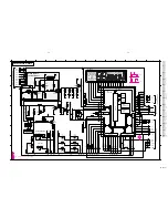
Page 22: ...47n 2354 47n 15n 2392 2302 1n 2301 1n 2341 100n 2323 100n 100n 2321 2303 100n 2355 100n 2356 100n 2310 2u2 2304 4u7 2305 47u 2322 22u 220u 2363 220u 2364 2300 47u 2351 330n 2352 330n 2306 4u7 4u7 2343 BC817 7368 BC817 7367 BC817 7365 BC817 7366 BC848 7344 6321 BAS216 6322 BAS216 7343 BC858C BC807 40 7301 3 2 1 10k lin 3300 9 8 6 7322 B 7322 A B D C 3 4 5 7322 D 2 1 13 74HC4066 74HC4066 10 11 12 74...

Page 23: ...41 C 3 3842 C 4 3844 C 4 3845 C 4 3846 D 4 3847 C 3 3848 C 4 3849 C 4 3854 D 4 3860 C 5 3861 C 5 3862 C 5 3863 C 5 3864 C 5 3866 D 5 3867 D 5 3868 D 5 3910 D 2 3925 C 2 3930 C 1 3931 C 2 3932 C 1 3933 C 1 3934 C 1 3980X B 2 3981X B 3 3982X B 3 3983X B 3 3984X B 3 3985X B 3 3986X B 3 3987X B 3 5368X A 4 5800 C 3 5950 D 2 5953 C 2 6250 E 4 6251 C 1 6321 A 4 6322 A 4 6390D A 5 6401 B 6 6450 B 5 6465 ...

Page 24: ...55K E 5 3856H E 5 3858G E 5 3859F E 5 3865E C 1 3869 D 5 3900 B 2 3901 B 2 3902 B 2 3903 B 1 3904X B 1 3905X B 1 3922 D 1 3923 C 1 3924 C 1 3926 C 1 3927 C 1 3935 D 2 3950 C 2 3951 C 2 5400 D 5 5920 C 2 5921 C 1 5951 C 2 5952 C 2 6431B D 6 6432B C 6 6433B C 6 6434B C 6 6951 C 1 6953X D 2 7279A D 4 7281 E 4 7282A E 4 7285 E 4 7287A E 4 7366 A 2 7368 A 2 7425 C 5 7831E B 2 7832E C 2 7851 D 5 7901 B ...

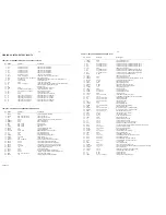
Page 25: ...INGE DOOR BATTERY AZ7562 AZ7566 414 4822 417 11348 HINGE DOOR BATTERY AZ7565 416 4822 443 10579 DOOR BATTERY AZ7565 416 4822 443 10581 DOOR BATTERY AZ7566 417A 4822 463 11028 SLIDER RESUME HOLD 417B 4822 463 11028 SLIDER ESA 418 4822 449 80147 CABINET ASSEMBLY AZ7562 418 4822 449 80137 CABINET ASSEMBLY AZ7565 418 4822 449 80139 CABINET ASSEMBLY AZ7566 419 4822 410 10285 BUTTON PLAY PRINTED 421 482...

Page 26: ...5 4 7µF 20 4V 2956 4822 126 11692 1µF 20 16V 2957 4822 124 11348 2 2µF 20 10V CAPACITORS 2958 4822 122 33496 100nF 10 63V 2959 4822 122 33496 100nF 10 63V 2960 4822 122 33496 100nF 10 63V 2961 5322 122 34123 1nF 10 50V 2962 4822 124 11348 2 2µF 20 10V 2963 5322 124 23675 4 7µF 20 4V RESISTORS 3254 4822 117 10833 10kΩ 1 0 1W 3255 4822 051 20473 47kΩ 5 0 1W 3262 4822 117 10833 10kΩ 1 0 1W 3263 4822 ...

Page 27: ... 10102 1kΩ 2 0 25W 3868 4822 051 10102 1kΩ 2 0 25W 3869 4822 051 10102 1kΩ 2 0 25W 3900 4822 051 20109 10Ω 5 0 1W 3901 4822 117 11383 12kΩ 1 0 1W 3902 4822 051 20682 6 8kΩ 5 0 1W 3903 4822 117 11374 120k 1 RC12H 3910 4822 051 20681 680Ω 5 0 1W RESISTORS 3922 4822 117 11437 8 2kΩ 1 0 1W 3923 4822 117 11139 1 5kΩ 1 0 1W 3924 4822 051 20563 56kΩ 5 0 1W 3925 4822 051 20109 10Ω 5 0 1W 3926 4822 051 201...

Page 28: ...2 GP1F366T OPTICAL OUTPUT 7281 4822 209 71448 NJM2903M 7300 4822 209 12989 TDA1548TZ N1 7320 4822 209 71448 NJM2903M 7322 5322 209 61482 PC74HC4066T 7400 4822 209 15453 TMP87CK20AF AZ7565 1 7425 4822 209 12991 PST9127N 7800 4822 209 12636 TDA1302T N1 7820 4822 209 33165 TDA1308T N1 7830 4822 209 90341 SAA7372GP M1 7850 4822 209 12992 SM5856AF 7851 4822 209 33699 MT4LC4001JDJ 8S 7852 4822 209 33699...

Reviews: