GC4870
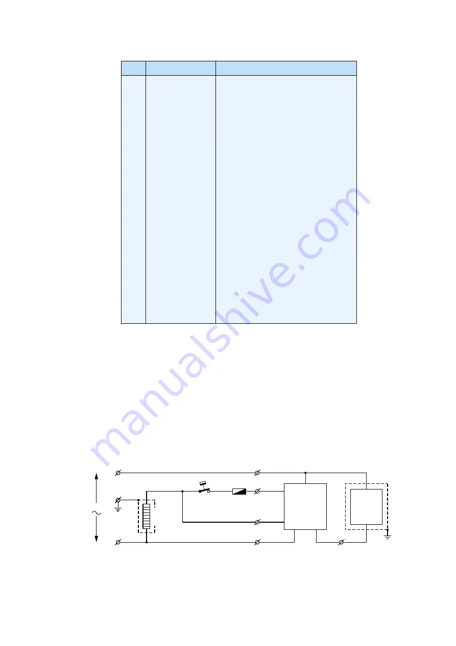
PARTS LIST& ELECTRICAL DIAGRAM
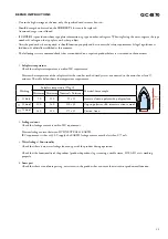
Brown
L
E
INPUT
Blue
N
White
ASO
Control
Unit
Red
Black
Heating
Element
Thermostat Thermal
Fuse
Ionizer
Module
4-5
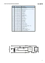
Pos
Service code
Description
1
2
3
4
5
6
7
8
9
10
11
12
13
14
15
16
17
18
19
20
21
22
23
24
4239 015 44881
4239 021 58681
4239 025 98250
4239 015 58881
4239 010 10400
4239 021 59121
4239 026 41271
4239 026 40501
4239 021 59101
4239 021 59041
4239 026 40181
4239 021 58841
4239 021 58881
4239 026 40101
4239 026 40141
4239 000 11121
4239 021 59141
4239 026 17320
4239 021 60181
4239 026 40261
4239 026 05990
4239 021 37070
4239 021 59131
4239 021 59061
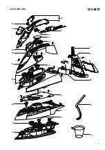
Cover inscribed
Soleplate mounted assy 230 V / 2400 W
Ryton spacer
Dosing seal
Heat shield
Backplate
Ball swivel
Backplate cover
Filling door assy
Inlay assy
Steam slider
Water tank assy
Housing assy
SOS knob
Spray knob
Cordset EU
ASO assy 230 V
Thermostat bush
Thermostat plate printed - Eng
Thermostat ring
Filling cup
Chamber top insert
Ionizer assy module 230 V
Ionic button printed


