A
A
B
B
C
C
D
D
E
E
4
4
3
3
2
2
1
1
Y 3
COAXOUT
FL
F R
R /V
B /U
G /Y
G /Y
CVBS
CVBS
COAXOUT
R /V
B /U
VCC_CVBS
VCC_6363
VCC_6363
VCC_6363
VCC_6363
VCC_6363
VCC
VCC_6363
VCC_CVBS
VCC_CVBS
ASPDIF
(4)
Y3
(4)
FR
(8)
FL
(8)
Y6
(4)
Y4
(4)
Y5
(4)
CVBS
Low Impedance
ㆪ
ow Impedance circuit with Real Line
Hight Impedance
˖
Hight Impedance circuit with Broken Line
Related PCB is match to SCH,but no hight Impedance circuit in Broken Line
COAXOUT OUTOUT
YUV High Impendance
Close to RCA connector
CTP36
D514
DIODE SMD BAV99
1
2
3
FB582 FB/0805
R1355
150R
C607
10uF/10V
0805-C
C627
100PF
CB1008
33PF
R1347
75 1%
CTP18
R535
100_1%
D522
DIODE SMD BAV99
1
2
3
0.1UF
C609
16V
10%
1
2
C626
100PF
CTP19
CTP39
CB1009
33pF/NC
R
W
W
R
P502
RCA2X2
RCA-407
1
2
3
4
5
6
R1354
150R
C510
10pF
D520
DIODE SMD BAV99
1
2
3
CTP38
Q212
BT3904
0.1UF
C610
16V
10%
1
2
R501 100R
D521
DIODE SMD BAV99
1
2
3
R1262
75 1%
+
CE605
47uF/16v
R536
91_1%
R1345
75 1%
C501
100pF
CB500
0.1uF
C509
10pF
R1403
33R/0
R1263
NC/0
R1398
2.4K
CB1006
33PF
CTP15
U913
FMS6363CS
IN1
1
IN2
2
IN3
3
VCC
4
GND
5
OUT3
6
OUT2
7
OUT1
8
R1356
150R
R1399
1.2K
CB968
0.1uF
FB581 FB/0805
R1350
7.5MR
L852
1.2uH
R
W
W
R
P505
RCA2X2
RCA-307
1
2
3
4
5
CB1002
0.1uF
CB1007
33PF
CTP17
R1349
7.5MR
L871
FB500R
0.1UF
C608
16V
10%
1
2
R1343
75 1%
CTP40
CTP16
R1348
7.5MR
R500
100R
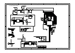
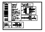
Main Board Electric Diagram: VIDEO OUTPUT & SPDIF OUTPUT
7-10
7-10
Summary of Contents for BDP3000
Page 43: ...Front Board Print layout Top and Bottom side 7 13 7 13 ...
Page 44: ...Power Board Print layout Bottom side Switch Board Print layout Bottom side 7 14 7 14 ...
Page 45: ...Power Board Print layout for BDP3000 93 Bottom side 7 14 7 14 ...
Page 46: ...Main Board Print layout Top side 7 15 7 15 ...
Page 47: ...Main Board Print layout Bottom side 7 16 7 16 ...
Page 55: ...REVISION LIST Version 1 0 Initial release for BDP3000 55 93 98 94 96 9 1 ...


