Items of Safety Attention
1-6
U
After unsoldering the unusable diode, nip its body and take it
out.
Bend the two pins and the diode is vertical to circuit board.
Check the polarity of the diode, then place its pins to the
correct location.
Pin the joint and solder it.
Check the weld carefully. If the surface of the weld is not
smooth, please solder it again.
R
-
Repair the warpage copper as following:
Use a sharp knife to scrape the unusable copper and the
unwanted solder off.
Make one side of the lead bent like a small “U”, then put the
“U” to IC pins and solder. Another side of the lead is extended
until overlap with the well copper then solder. Cut the unwand
lead.
T
D D
No sound or sound distorted when playing, please check the
DVD part.
N
Before operating, read these notes as following to prevent the
static charges damageing the laser head when reading the
laser led.
Lay an electric rug on the working table and the replaced parts
are packed in black package.
The electric rug is grounding by put on the electric base.
Then put your hand on the electric rug and connect the static
handle with the electric rug. Make sure the electric rug and the
working table are grounding.
During the operating, do something such as operating on the
electric rug to avoid the static charges touching the laser parts.
After that, you can begin to take the laser parts down.
When replace the laser parts, please do something to make a
short circuit and remenber to cut the short circuit off after
replacing.
Summary of Contents for BDP9500
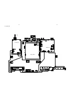
Page 16: ...7 2 7 2 MCU Board Layout Diagram ...
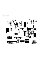
Page 18: ...8 2 8 2 VFD Display Board Layout Diagram ...
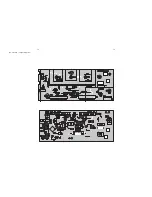
Page 22: ...11 2 11 2 Output Board Audio Layout Diagram ...
Page 24: ...12 2 12 2 Power Board Layout Diagram ...
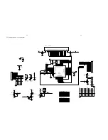
Page 32: ...13 8 13 8 HDMI Board Scalar Layout Diagram ...
Page 42: ...14 10 14 10 Decoder Board Layout Diagram ...
Page 43: ...15 1 15 1 Exploded View ...


