Diagnostic Software Utilities
5-34
CardioMD Service Manual
1MAN0158-H11 04-2005 CSIP Level 1
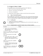
5.6.2
EDC Module Diagnostics
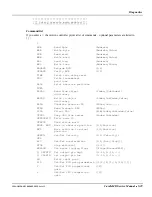
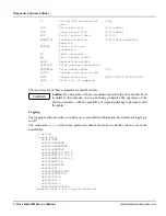
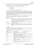
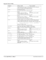
The EDC board has a serial port that can be used for troubleshooting purposes using various
utilities resident within the EDC firmware. This section identifies only a few commands that may
be helpful in troubleshooting CardioMD system related failures.
5.6.2.1
Tools Required
•
NULL modem serial interface cable (DB9-female to DB9-female)
•
When using a laptop acquisition PC (CardioMD Series III): An USB to RS 232 adapter, part
no. 3ACQ1669.
5.6.2.2
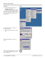
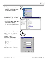
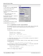
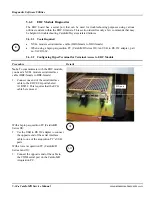
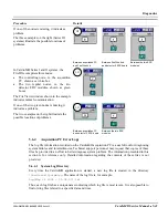
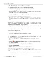
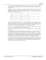
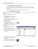
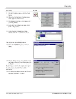
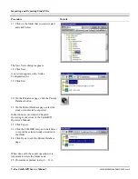
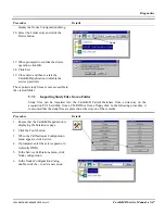
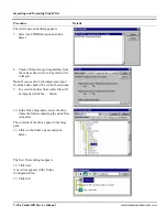
Configuring HyperTerminal for Terminal Access to EDC Module
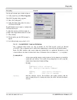
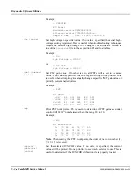
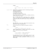
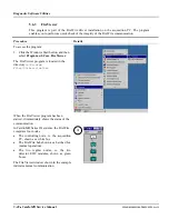
Procedure Details
Note
. To communicate with the EDC module,
you need a NULL modem serial interface
cable (DB9-female to DB9-female).
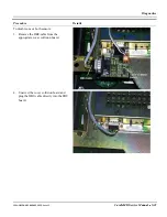
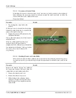
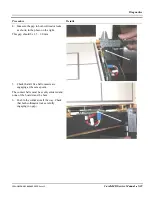
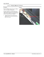
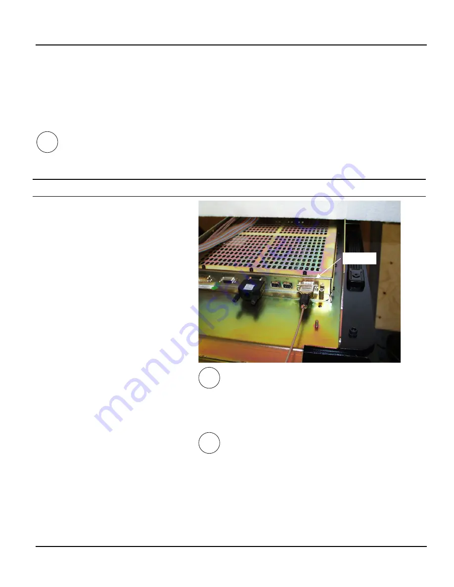
1.
Connect one end of the serial interface
cable to the EDC ECG port labeled
A1 RS232. This requires that the ECG
cable be removed.
With a laptop acquisition PC (CardioMD
Series III):
2.
Use the USB to RS 232 adapter to connect
the opposite end of the serial interface
cable to one of the acquisition PC’s USB
ports.
With a tower acquisition PC (CardioMD
Series I and II):
3.
Connect the opposite end of the cable to
the COM1 serial port on the CardioMD
Acquisition PC.
I, II
III
ECG port
III
Summary of Contents for CARDIOMD
Page 1: ...CARDIOMD SERVICE MANUAL 1MAN0158 H11 04 2005 CSIP Level 1 ...
Page 10: ...Introduction x CardioMD Service Manual 1MAN0158 H11 04 2005 CSIP Level 1 ...
Page 16: ...Safe Operating Practices 1 6 CardioMD Service Manual 1MAN0158 H11 04 2005 CSIP Level 1 ...
Page 164: ...Detector Calibration Files 5 60 CardioMD Service Manual 1MAN0158 H11 04 2005 CSIP Level 1 ...
Page 328: ...Installation Procedures 9 38 CardioMD Service Manual 1MAN0158 H11 04 2005 CSIP Level 1 ...
Page 348: ...Planned Maintenance Procedures 11 6 CardioMD Service Manual 1MAN0158 H11 04 2005 CSIP Level 1 ...
Page 465: ......


