Installation
1MAN0158-H11 04-2005 CSIP Level 1
CardioMD Service Manual
8-45
Procedure Details
2.
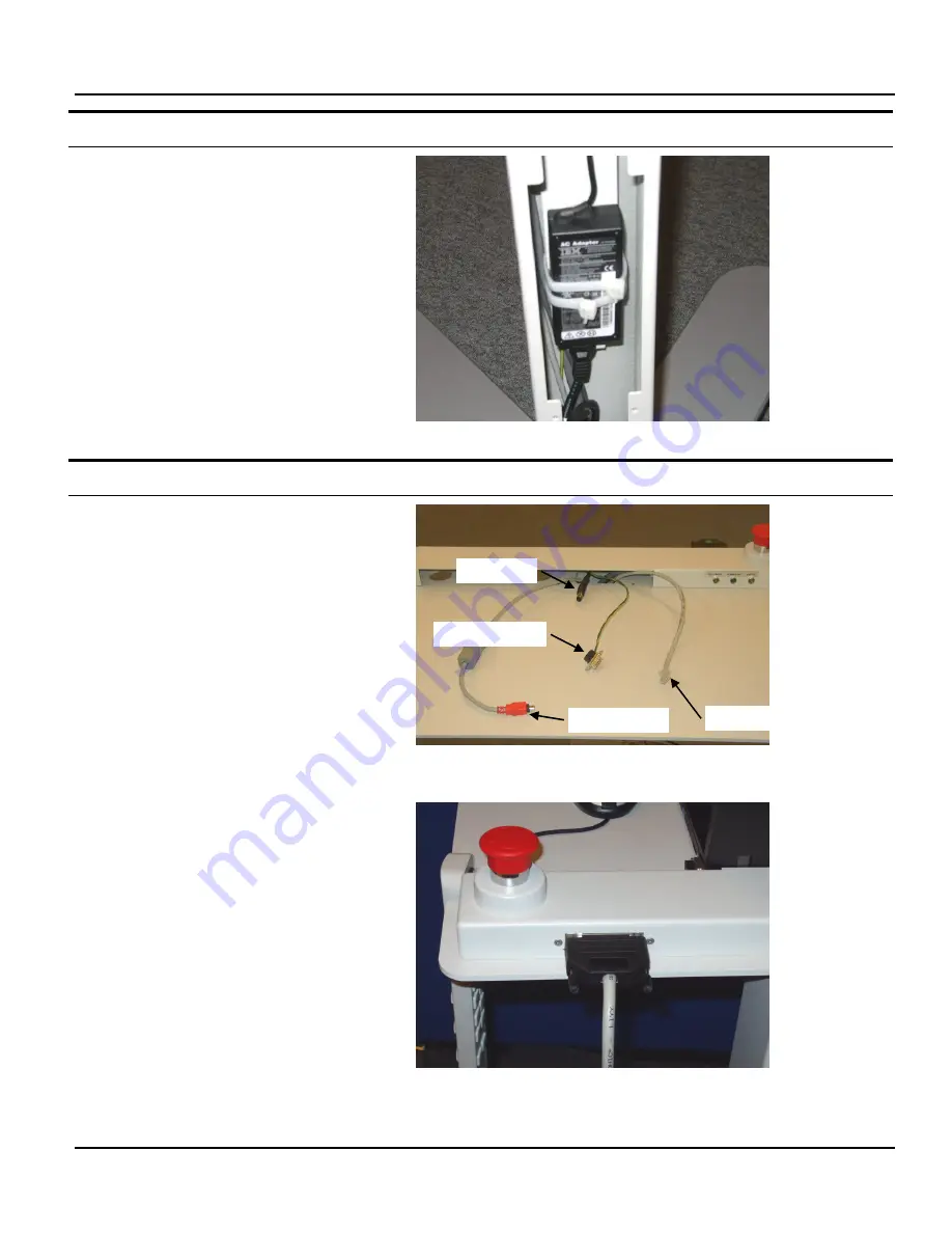
Use a couple of Ty-Wraps to fix the laptop
power supply to the bracket inside the cart
stand.
3.
Route the power connector for the laptop
PC up and through the hole in the top
plate.
4.
Connect the power supply mains
connector to the IEC power connector on
the gantry cable.
5.
Mount the cover on the rear of the cart
stand.
To connect the laptop PC and hand controller, proceed as follows:
Procedure Details
1.
Connect the FireWire cable to the
FireWire connector on the laptop PC.
2.
Connect the power cable to laptop PC’s
power input.
3.
Connect the DB9 connector to the laptop
PC’s monitor output.
This connection is only required to ground the
laptop PC for EMI/EMC reasons.
4.
Connect the Ethernet cable to the laptop
PC’s network connector.
5.
Connect the external mouse to a USB port
on the laptop PC.
6.
Connect the hand controller to the DB25
connector on the rear side of the cart top
plate, next to the E-Stop button.
FireWire cable
Power cable
Ground connector
Ethernet cable
Summary of Contents for CARDIOMD
Page 1: ...CARDIOMD SERVICE MANUAL 1MAN0158 H11 04 2005 CSIP Level 1 ...
Page 10: ...Introduction x CardioMD Service Manual 1MAN0158 H11 04 2005 CSIP Level 1 ...
Page 16: ...Safe Operating Practices 1 6 CardioMD Service Manual 1MAN0158 H11 04 2005 CSIP Level 1 ...
Page 164: ...Detector Calibration Files 5 60 CardioMD Service Manual 1MAN0158 H11 04 2005 CSIP Level 1 ...
Page 328: ...Installation Procedures 9 38 CardioMD Service Manual 1MAN0158 H11 04 2005 CSIP Level 1 ...
Page 348: ...Planned Maintenance Procedures 11 6 CardioMD Service Manual 1MAN0158 H11 04 2005 CSIP Level 1 ...
Page 465: ......


