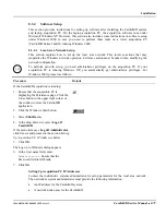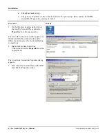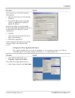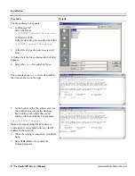
Installation
8-72
CardioMD Service Manual
1MAN0158-H11 04-2005 CSIP Level 1
Procedure Details
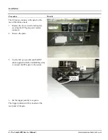
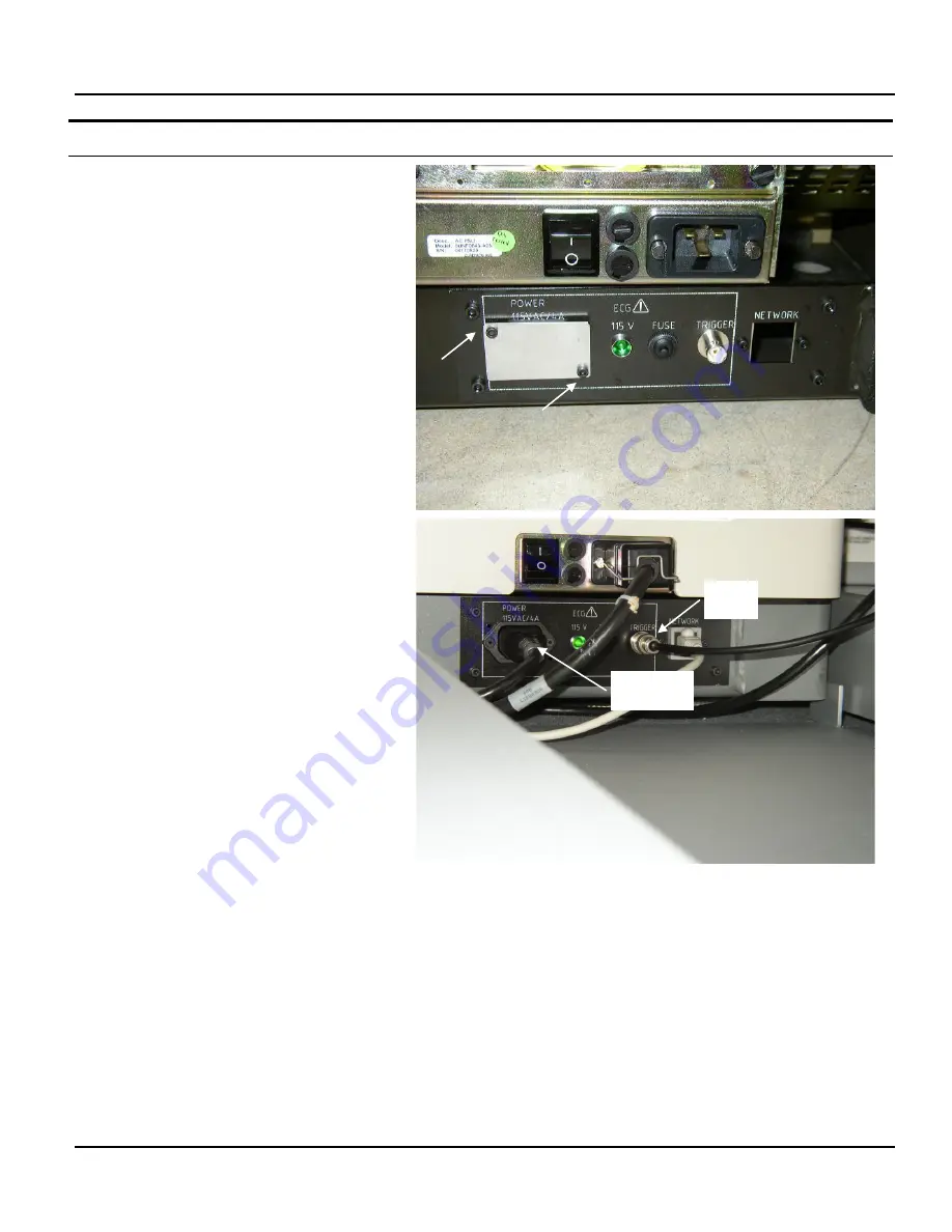
The ECG gate connects to the panel on the
rear of the table console.
3.
Remove the two screws from the plate
covering the ECG gate power output
connector.
4.
Remove the plate.
5.
Use the IEC power cable and the BNC
cable supplied with the CardioMD system
to connect the ECG gate to the system.
6.
Set the trigger polarity to
negative
.
The trigger polarity switch is located at the
rear panel of the gate.
ECG
trigger
ECG gate
power cable
Summary of Contents for CARDIOMD
Page 1: ...CARDIOMD SERVICE MANUAL 1MAN0158 H11 04 2005 CSIP Level 1 ...
Page 10: ...Introduction x CardioMD Service Manual 1MAN0158 H11 04 2005 CSIP Level 1 ...
Page 16: ...Safe Operating Practices 1 6 CardioMD Service Manual 1MAN0158 H11 04 2005 CSIP Level 1 ...
Page 164: ...Detector Calibration Files 5 60 CardioMD Service Manual 1MAN0158 H11 04 2005 CSIP Level 1 ...
Page 328: ...Installation Procedures 9 38 CardioMD Service Manual 1MAN0158 H11 04 2005 CSIP Level 1 ...
Page 348: ...Planned Maintenance Procedures 11 6 CardioMD Service Manual 1MAN0158 H11 04 2005 CSIP Level 1 ...
Page 465: ......


