Detectors
3-30
CardioMD Service Manual
1MAN0158-H11 04-2005 CSIP Level 1
THRESHOLD
CONTROL
VOLTAGE
HIDYN ON X-E STRIP
HIDYN ON Y STRIP
LODYN ON Y STRIP
THRESH ON Y STRIP
THRESH ON X-E STRIP
LODYN ON X-E STRIP
ENERGY
SIGNAL
LOW DYN
CONTROL
VOLTAGE
HIGH DYN
CONTROL
VOLTAGE
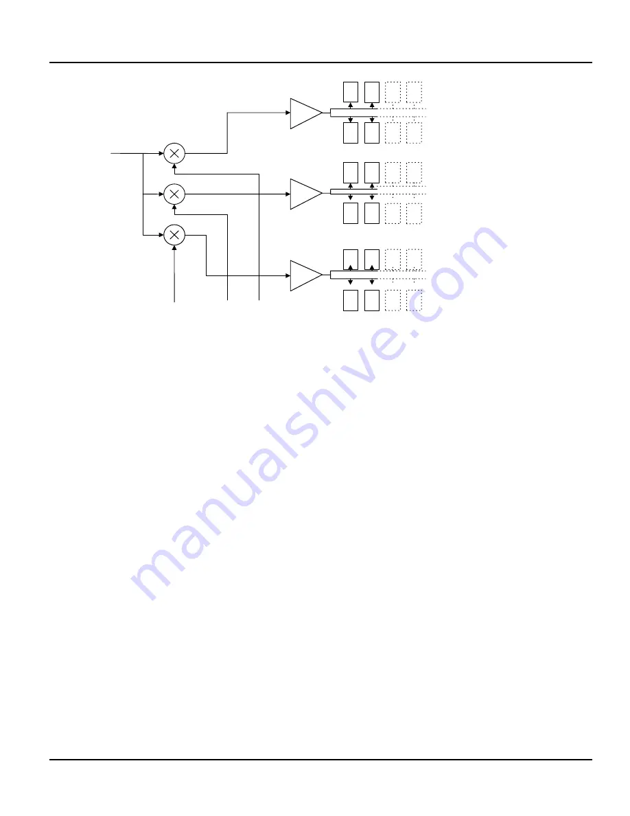
Figure 3.23 Schematic block diagram of DynCor- and threshold drivers
3.3.6.3
Y Board
The Y Board sums the output from five overlapping groups of PMT’s in the Y direction. Each
group sum is subjected to a DynCor circuit succeeded by a threshold similar to that on the X-E
board.
The five group sums are fed into a resistor matrix which feeds into two summing nodes, Y+ and
Y–.
Note that the Y board also carries a +5 V linear regulator and a –5 V linear regulator that supplies
the analog multipliers on the X-E board.
Summary of Contents for CARDIOMD
Page 1: ...CARDIOMD SERVICE MANUAL 1MAN0158 H11 04 2005 CSIP Level 1 ...
Page 10: ...Introduction x CardioMD Service Manual 1MAN0158 H11 04 2005 CSIP Level 1 ...
Page 16: ...Safe Operating Practices 1 6 CardioMD Service Manual 1MAN0158 H11 04 2005 CSIP Level 1 ...
Page 164: ...Detector Calibration Files 5 60 CardioMD Service Manual 1MAN0158 H11 04 2005 CSIP Level 1 ...
Page 328: ...Installation Procedures 9 38 CardioMD Service Manual 1MAN0158 H11 04 2005 CSIP Level 1 ...
Page 348: ...Planned Maintenance Procedures 11 6 CardioMD Service Manual 1MAN0158 H11 04 2005 CSIP Level 1 ...
Page 465: ......


