CM-150 CA Product Guide
8
triggering, and one or more CM-150 CA devices. While your specific lighting
network configuration may allow for additional devices, we recommend that you limit
individual Ethernet runs to 15 or fewer CM-150 CA, DIN Rail Mount devices. For
additional CM-150 CA devices in a network, use additional Ethernet switch ports.
Ethernet
Switch
Light
System
Manager
PC
CM-150 CA
iColor Flex LMX gen2
Electrical Configuration Guidelines
The maximum number of nodes each CM-150 CA can support depends on the
luminaire type, as well as on additional configuration details such as node spacing
and leader cable length. The table in the margin lists the maximum number of Flex
nodes each CM-150 CA can support, assuming a suitable power supply is used. Keep
in mind that these figures, provided as a guideline, are accurate for the specified
configuration only, and that changing the configuration can affect the number of
nodes per CM-150 CA.
CM-150 CA must be installed in a location that allows air to move freely around the
device. Startup and operating temperatures are rated to 50 °C (122 °F). Exceeding
this temperature limit may cause device damage or failure.
Data Configuration Guidelines
In addition to maximum run lengths determined by the electrical configuration, each
CM-150 CA imposes maximum run lengths based on data integrity.
When selecting mounting locations for the CM-150 CA devices in your installation,
keep cable length maximums in mind:
CM-150 CA
iColor Flex LMX gen2
• In Ethernet networks, maximum data cable lengths are 100 m (328 ft) between
Ethernet devices without a repeater (for example, controller to switch, or switch
to CM-150 CA).
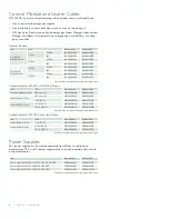
Maximum nodes per CM-150 CA
Luminaire
Nodes per
port
Nodes per
CM-150 CA
eW Flex Compact
75 nodes
150 nodes
eW Flex Micro
75 nodes
150 nodes
iColor Flex LMX gen2 75 nodes
150 nodes
iColor Flex MX gen2
75 nodes
150 nodes
iW Flex Compact
75 nodes
150 nodes
Ethernet maximum data cable length
between CM-150 CA devices
100 m (328 ft) Max
100 m (328 ft) Max

