Amplifier
Total output power 2 x 5 W RMS
Frequency
response
125 Hz - 16 kHz, ± 3 dB
Signal to noise ratio > 60 dB
MP3 link input
0.5 V RMS 20 k
Disc
Laser type
Semiconductor
Disc diameter
12 cm /8 cm
Support disc
CD-DA, CD-R, CD-RW,
MP3-CD, WMA-CD
Audio DAC
24 Bits / 44.1 kHz
Total harmonic
distortion
< 1.5%
Frequency
response
60 Hz -16 kHz (44.1 kHz)
Signal to noise ratio > 75 dBA
Tuner
Tuning range
FM: 87.5 - 108 MHz
Tuning grid
50 KHz
Number of presets
20
Speakers
Speaker driver
4” woofer
Speaker impedance
5 W, 3
General information
AC power
230-240 V~, 50 Hz
Operation Power
Consumption
25 W
Standby Power
Consumption
< 2 W
Eco Power Standby
Power Consumption
< 1 W
USB Direct
Version 2.0/1.1
Dimensions
- Main Unit
(W x H x D)
542 x 238 x 102 mm
Weight
- Main Unit
3.935 kg
TECHNICAL SPECIFICATION
1 - 2
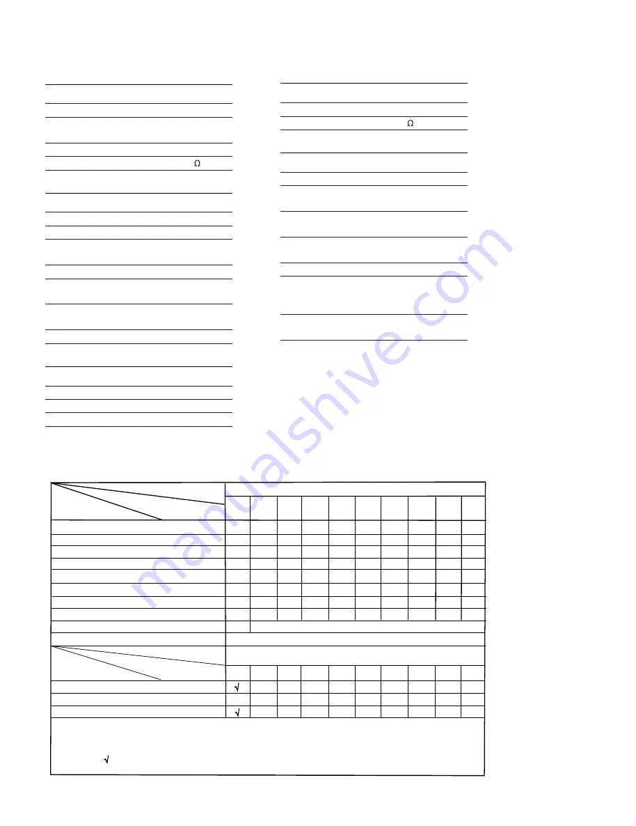
Type /Versions:
Features
Board in used:
DCM 276
Service policy
DISPLAY BOARD
MAIN BOARD
POWER BOARD
KEY BOARD
* TIPS : C -- Component Lever Repair.
M -- Module Lever Repair
-- Used
/05
/12
/55
8
9
/
1
6
/
8
5
/
Feature diffrence
RDS
VOLTAGE SELECTOR
ECO STANDBY - DARK
C
C
Type /Versions:
DCM 276
/05
/12
/55
8
9
/
1
6
/
8
5
/
C
C
VERSION VARIATION
3
9
/
3
9
/
MCU BOARD
IPOD JACK BOARD
SW BOARD
C
C
C
C
C&M
C&M
C
C&M
C
C
All manuals and user guides at all-guides.com
Summary of Contents for DCM276
Page 7: ...SET BLOCK DIAGRAM 3 1 All manuals and user guides at all guides com ...
Page 8: ...SET WIRING DIAGRAM 4 1 MCU PCB MCU PCB All manuals and user guides at all guides com ...
Page 10: ...6 1 6 1 CIRCUIT DIAGRAM MAIN BOARD PART 1 All manuals and user guides at all guides com ...
Page 12: ...6 3 6 3 CIRCUIT DIAGRAM MAIN BOARD PART 3 All manuals and user guides at all guides com ...
Page 13: ...6 4 6 4 CIRCUIT DIAGRAM MAIN BOARD PART 4 All manuals and user guides at all guides com ...
Page 14: ...6 5 6 5 CIRCUIT DIAGRAM MAIN BOARD PART5 All manuals and user guides at all guides com ...
Page 17: ...CIRCUIT DIAGRAM MCU BOARD 7 1 7 1 All manuals and user guides at all guides com ...
Page 18: ...7 2 7 2 LAYOUT DIAGRAM MCU BOARD TOP SIDE All manuals and user guides at all guides com ...
Page 19: ...LAYOUT DIAGRAM MCU BOARD BOTTOM SIDE 7 3 7 3 All manuals and user guides at all guides com ...
Page 22: ...8 3 8 3 LAYOUT DIAGRAM KEY BOARD All manuals and user guides at all guides com ...
Page 23: ...9 1 9 1 CIRCUIT DIAGRAM POWER BOARD All manuals and user guides at all guides com ...
Page 24: ...9 2 9 2 LAYOUT DIAGRAM POWER BOARD All manuals and user guides at all guides com ...
Page 25: ...10 1 10 1 CIRCUIT DIAGRAM iPod JACK BOARD All manuals and user guides at all guides com ...
Page 28: ...12 1 12 1 SET EXPLODED VIEW All manuals and user guides at all guides com ...


