Alignments
EN 74
DPTV565 AA
8.
1.
During the IF AFC-parameter adjustment, one can see
OSD feedback on the screen.
2.
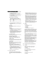
The OSD feedback can give 4 kinds of messages:
3.
The first item (IN/OUT) informs you whether you are in or
out of the AFC-window.
4.
The second item (HIGH/LOW) informs you whether the
AFC-frequency is too high or too low.
Table 8-2 OSD feedback of AFC alignment
1.
Adjust the IF AFC parameter until the first value is within
the AFC window (= IN).
2.
Next, adjust the IF AFC parameter until the second value
is LOW.
IF LPRIME AFC
Same procedure as described above but with other signal
source (SECAM L').
TUNER AGC
1.
Connect the RF output of a video pattern generator to the
antenna input.
2.
From the generator, input a PAL B/G TV signal with a
signal strength of approximately 2 mV and a frequency of
475.25 MHz (PAL) or 61.25 MHz (NTSC).
3.
Measure the DC voltage on pin 1 of the (main) Tuner. You
can adjust this voltage by adjusting the TUNER AGC item
in the SAM menu. Alignment is correct when the DC
voltage is just below 3.5 V.
IF AFC TUNER 2 (if present)
Use the same procedure as described above (under IF AFC)
with the set switched to the DW source.
IF LPRIME AFC TUNER 2 (if present)
Use the same procedure as described above (under IF
LPRIME AFC) with the set switched to the DW source.
TUNER AGC TUNER 2
Use the same procedure as described above (under TUNER
AGC) with the set switched to the DW source. Measure on pin
“1” of the DW Tuner.
BLEND INTENSITY
Use this alignment when you replace the microcontroller or the
HOP. It aligns the level of transparency of the menu-picture
blended into the main-picture.
Position the "Brightness", "Contrast", and "Colour" setting in
the middle position (in the customer "Picture" menu).
1.
Apply a signal with a 100 % white video pattern (white
raster).
2.
Connect an oscilloscope to pin 8 of connector 1298 of the
CRT panel and measure the Red output level.
3.
Align the BLEND INTENSITY parameter so that the
blended signal is 65 % of the black-white amplitude. This
will be about 1.3 V (blended signal) versus 2 V (full white
signal).
4.
The parameter can be adjusted from 0 to 31.
8.3.2
LUM. DEL. (Luminance Delay)
With this alignment, you place the luminance information
exactly on the chrominance information (brightness is pushed
onto the colour). Use a colour bar / grey scale pattern as test
signal.
•
LUM. DELAY PAL BG: Apply a PAL BG colour bar / grey
scale pattern as a test signal. Adjust this parameter until
the transients of the colour part and black and white part of
the test pattern are at the same position. Default value is
"9".
•
LUM. DELAY PAL I: Apply a PAL I colour bar/grey scale
pattern as a test signal. Adjust this parameter until the
transients of the colour part and black and white part of the
test pattern are at the same position. Default value is "9".
•
LUM. DELAY SECAM: Apply a SECAM colour bar/grey
scale pattern as a test signal. Adjust this parameter until
the transients of the colour part and black and white part of
the test pattern are at the same position. Default value is
"11".
•
LUM. DELAY BYPASS: apply a NTSC colour bar/
greyscale pattern as a test signal. Adjust this value until the
transients of the colour and black and white part of the test
area are at the same position. Default value is "10".
8.3.3
GDE SAM
Specifications:
•
Set display mode in service mode.
•
Service blanking.
•
Set geometry.
•
Preset picture.
•
Set white tone.
•
Convergence disable for setting geometry.
The GDE SAM mode (GDE = Generic Display Engine), allows
the Service Technician to set Geometry and White Tone (Grey
Scale). This mode is controlled by the GDE microprocessor
located on the ASC module. These settings are stored in an
EEPROM located on the ASC module. The GDE SAM displays
the Software version of the GDE microprocessor and the GDE
Errors.
There are three settings for Geometry in the 4x3 aspect ratio
sets and two for the 16x9 aspect ratio sets.
The signal for the 480p mode can be applied to the set via the
HD YPbPr inputs or from the SSB when the set is in the NTSC
mode. All Geometry alignments for this mode should be done
with an NTSC signal selected.
Adjustments for the 1080i should be done with an HD 1080i
signal applied to the set. The 4x3 aspect ratio sets have both a
Full and Compressed mode that requires alignment.
The Service Blanking selection (SERV BLANK) will blank the
bottom half of the picture. This selection is useful when
adjusting the Yokes to level the picture.
The Clamp Pulse should be set to Normal for a 480p or NTSC
signal. It should be set to 1080i for an HD signal.
The Convergence Processor selection will enable or disable
Convergence drive. Convergence should be disabled when
performing Cantering or Geometry alignments.
8.4
Convergence and Geometry Adjustments
8.4.1
Introduction
If the ACS module has been replaced, the following
adjustments will be required in the order as shown:
1.
Geometry.
2.
Convergence.
3.
Grey Scale (White Tone).
If the Large Signal Board (LSB) has been changed the
following adjustment are required:
1.
Geometry.
2.
Convergence.
If one or more CRTs have been replaced:
1.
Geometry.
2.
Convergence.
AFC-window
AFC-frequency vs. reference
Out
High
In
High
In
Low
Out
Low


