Circuit Descriptions, List of Abbreviations, and IC Data Sheets
EN 79
DPTV565 AA
9.
9.
Circuit Descriptions, List of Abbreviations, and IC Data Sheets
Index of this chapter:
9.1 Introduction
9.2 Power Supplies
9.3 Video
9.4 Audio
9.5 Control/OSD
9.6 List of Abbreviations
9.7 IC Data Sheets
9.1
Introduction
Two new chassis are being introduced for the Asia Pacific
region in the 2005 model year. The table below lists the Model
and Chassis numbers.
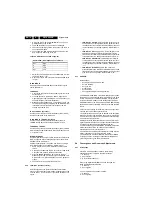
Table 9-1 Model and chassis overview
All the chassis have multi-system tuning capability. The set has
the capability of displaying the 1080i, 480p, and 576p high
definition component analogue inputs. The 1fH RF inputs can
be PAL or SECAM. The 1fH AV inputs can be YPbPr-
component, composite, or SVHS.
Some of the highlights are:
•
TV-off air systems (PAL and SECAM).
•
Korean sets NTSC only.
•
NTSC (3.58 - 4.5 MHz).
•
NTSC (4.43 - 5.5 MHz).
•
PAL B/G, PAL D/K, PAL I, PAL M, PAL N.
•
SECAM B/G, SECAM D/K, SECAM K1.
•
HD signal inputs are analogue.
•
Component in.
The sets have 1fH multi-system composite, SVHS, and
component inputs. The External 1fH or TV RF signals are fed
to the Picnic and Eagle circuits, where the user can select
between 100 Hz Digital Scan or Double lines.
External input systems:
•
NTSC 3.58 MHz
•
NTSC 4.43 MHz
•
PAL
•
SECAM
•
480p, 576p, 1080i, component input
•
480p, 1080i Korean set
All of the sets, based on the PEMG, have a 4x3 aspect ratio,
except the 46” version which has a 16x9 aspect ratio. There are
eight different scan modes with each requiring separate
geometry and convergence settings. The modes are PAL
100Hz, PAL 75 Hz, 576p, 576p DVD, 480p, 480p DVD, 1080i.
Each of the modes has separate geometry and convergence
data, stored in the NVM, located on the ACS (Automatic
Convergence System) module.
Sound System processing is performed on the SSB (Small
Signal Board). This is a multi-system sound decoding
processor. The audio amplifier is located on the SSM (Small
Signal Module). This is a 24 Watt (2 x 12 Watts) digital
amplifier. There is also a Headphone output, located on the
Side Jack Panel. The headphone amplifier is located on the
SSM.
Sound system:
•
30 W (2x15W) Audio.
•
Headphone Out.
•
Speaker "on"/Off.
9.2
Power Supplies
The Rectifiers and Standby Supplies are located on the AC
Input Panel. The Main Power Supply is located on the Large
Signal Board (LSB).
In the table below, the models are listed with their respective
voltage requirements. Auto Multi Voltage sets have a voltage
range of 90 to 276 V.
Table 9-2 Voltage range overview
9.2.1
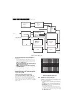
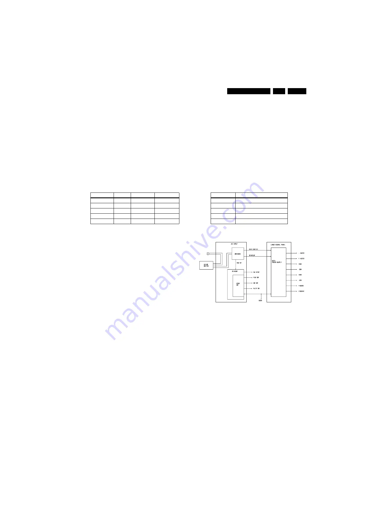
Overall Power Supply Block
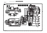
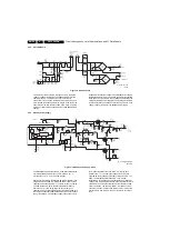
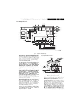
Figure 9-1 Power supply block diagram
The bridge rectifiers and Standby supply are located on the AC
Input Panel. The Main Power supply is located on the Large
Signal panel. A mains switch switches the AC power to the
bridge rectifier, located on the AC Input panel. This switch must
be turned "on", to place the set in the Standby mode. The
Standby supply produces a +5 Volt standby voltage. In the
Standby mode, the set consumes less than 1 W of power.
When the set is turned "on", the microprocessor on the SSB
causes the STANDBY line to go "low", switching the Standby
supply to p15 V, +9 V, and +5.2 V sources. It also turns
the Main Power supply "on", which produces the Audio, +35, -
35, +22, -22, +130 V_S, and +130 V_HV supplies. The +130
V_S supply is for the Horizontal Output section. The +130
V_HV supplies power to the High Voltage section.
Model
Chassis
Aspect Ratio Destination
43PP7445/69 DPTV565
4x3
Singapore
43PP7445/93 DPTV565
4x3
China
46PP7745/93 DPTV565
16x9
China
50PP7445/69 DPTV465
4x3
Singapore
50PP7445/93 DPTV465
4x3
China
Model
Voltage Range
43PP7445/69
160 - 276V nominal 230 V
43PP7445/93
160 - 276V nominal 230 V
46PP7745/93
160 - 276V nominal 230 V
50PP7445/69
160 - 276V nominal 230 V
50PP7445/93
160 - 276V nominal 230 V
E_15000_066.eps
151004

