…………………………………………………....………………………………..….....................
…………………………………………………....………………………………..…..................
………………………
DTP170- NA
Revolution Color
Touchscreen
Installation Instructions
Installation Instructions
…………………………………………………....………………………………..…...............
………………………
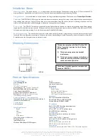
Electrical Connections
Connect Data Cable in a ‘Daisy Chain’
Mounting Location
Install in a dry, well-ventilated location indoors in an office-clean area.
Data Cable
Connecting Method
The recommended connecting method is to ‘daisy chain’ devices (i.e., starting
at the first device, then looping in and out of devices, with a single cable
terminating at the last device. There should not be any spurs or stubs, and
only the first and last device should terminate 1 cable, all other devices should
terminate 2 cables). Devices may be wired in any order. Data cable is Class 2
and must be separated from line (mains) conductors per NEC. A data cable
that is connected to an energized device is live. Do not cut or terminate live
data cables.
For longer cable runs, the Data Cable segregation from any
Mains Cables of 12” is recommended to minimize noise coupling. If the Data
Cable has to cross over any Mains Cables, it should do so at a 90° angle.
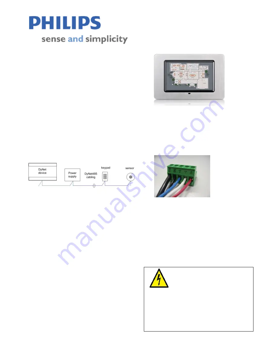
Data Cable Termination
1.
Strip off between 1” and 2-1/4” of outer jacket.
2. Cut shield (foil or braid) flush to outer jacket. DO NOT cut drain
wire.
3.
Fit 1/16” heat-shrink tubing over drain wire, leaving 1/8” of wire
exposed for termination.
4.
Fit 1” length of 3/8” heat-shrink tubing over the entire cable.
Position it so that 3/4” of its length is over cable jacket, and 1/4” of
its length is over loose connectors.
5.
Strip 1/8” of insulation from each of the conductors.
6. Terminate conductors on the terminal block.
7. Shrink remaining heat-shrink tubing.
8. Apply the appropriate ID label to the cable at the end of the outer
heat-shrink tubing.
Cable color coding
Black: ground
Red: 24V
Blue/white pair: Blue for DATA+ White for DATA-
Recommended cable types
Belden:
#1502R
Belden:
#1502P
Shielded or Screened cable is recommended for DyNet networks.
UTP Cat 5 cables are acceptable under certain conditions and if installed
in conduit. See DyNet Cable Guidelines.
WARNING
This is a Class 2 device and must only be
connected to Class 2 wiring.
To reduce the risk of fire or electric shock and to avoid damage to the unit,
before installation or servicing disconnect network & device power at circuit
breakers or remove fuses. It is recommended that an electrician perform this
installation.
Do not expose this device to rain or moisture. Connect the cable shield to the
provided shield termination on a device connection port. If no shield
termination is provided on a device, connect the cable shield to equipment
grounding conductor of the supplying branch circuit(s). Installation,
programming and maintenance must be carried out by qualified personnel.
Data Cable Permanent Connections


