background image

1

1

2

2

3

3

4

4

5

5

6

6

A

A

B

B

C

C

D

D

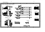
(S-)VIDEO OUT

CVBS OUT

TO FRONT BOARD

PSCAN OUT

TO KARAOKE-ECHO
BOARD

America,Apmea,China

L:Listening music

H:KARAOKE

TO SCART BOARD

EUROPE

safety
resistor

(OPEN)

TO DECODE BOARD J5

TO DECODE BOARD J4

TO DECODE BOARD J3

POWER+AV BOARD

2V5

4V

TO MIC1

POWER BOARD

C

MUTE

PCON

VA-

GND

B/CB

G/Y

MIC

FL

SCART_RGB

FR

DMUTE

CVBS

VCC

FL

SPDIF

AUDIO_DR

B/Cb

Y

VA+

SCART_SW

Y

MUTE

B/Cb

MUTE

R/Cr

SCART_SW

+5V

G/Y

GND

FMUTE

MICMUTE

GND

AUDIO_DL

GND

C

SCART_RGB

CVBS

R/Cr

+12V

FMUTE

GND

R/CR

G/Y

GND

FR

CVBS

DMUTE

AUDIO_DR

MIC1

MUTE

MUTE

MIC

VA+

VA-

MICMUTE

AUDIO_DL

+5V

SPDIF

VA-

PCON

VA+

VCC

+5V

FR

FL

VA+

+5V

VCC

VA-

VA-1

+5V

VA+1

VA+1

VA+1

VA-1

VA-1

+5V

+5V

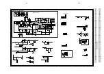
R309

56 1/4W

R320

220

+

C305

68uF/400V

C513

104

R324

1.5k 1%

D311

31DQ06

T301

12

14

8

1

10

4

6

9

13

2

5

11

7

15

R502

100K

R517
470R

+

C330
10uF/16V

C323
0.1uF

C515

104

ZD301
BZX79C10

CON507

CVBS_OUT

1
2
3

C506

10uF/16V

D501

IN4148

CON510

STEREO OUT

1
2
3

R524
10K

+

C328

470uF/16V

C331
0.1uF

PAS

L303

3.3uH

Q505
C9015

1

2

3

C311

102/400Vac

C312

222/400Vac

R511

100K

+

C315

100uF/25V

C308
470p

Q509
C9014

D301

1N4007

C522

104

+

C333

470uF/16V

R323
1.6k 1%

CON502
PITCH=2.0*5

1
2
3
4
5

1
2
3
4
5

R533

100K

CON509

S(VIDEO) OUT

1
2
3
4

C317
0.1uF

U304
AMS2910

2

3

1

VO

IN

GND

C514

100uF/16V

R322
2.2k

C327
0.1uF

Q304
8050

C505
152

R327

1.1K 1%/OPEN

R513
3K3

R507
10K

R512

10K

R316

220

D313
FR104

CON301
AC INPUT

1

2

++

Q508
C9015

PAS

R545

10R

Q503
C9014

R519

2K

L301
58mH

D310
RU3YX

COAX1

1
2
3

CON501

PITCH=2.0*12

1

2

3

4

5

6

7

8

9

10

11

12

C526

330P

C503

10uF/16V

R317
220

ZD303
BZX79C10V

R321

220

R529
120R

CON504

PITCH=2.0*8

1

2

3

4

5

6

7

8

R303
6.8k

C310
0.1uF

R523

1K

U301
TEA1523P

4

5

1

2

8

3

6

REG

AUX

VCC

GND

Drain

RC

Source

R538

33K

C517
104

D312
FR104

R307

68k

+

C316

100uF/25V

C301

0.22uF/250Vac

CON512

PITCH=2.0*4

1
2
3
4

1
2
3
4

Q306
9014

R514
470R

R304

1 1/4W

R325
2.2k

D306
FR104

R530
150R

+

C326

1000uF/16V

C504
180P

+

C309

10uF/50V

C304
0.22uF

C501

10uF/16V

ZD305
BZX79C10

D314
IN4148

C509
180P

C525

330P

R531
100R

R522
68R

C511
100P

D503

IN4148

D304

1N4007

C508
10uF/16V

R521

10K

R516

2K

V+

V-

U501-2

4558

5

6

7

8

4

R306
150 1/4W

+

C324

1uF/100V

R505
20K

C512

100P

L302
0.6uH

R302
6.8k

D305
1H8

R520
1K

D504

IN4148

C524
100P

L304

10uH

C302

NU

C507

102

U302
PC123Y

1

2

4

3

R532
10K

L305

10uH

C325
0.1uF

R509
10K

R308

680k

PAS

R534
100K

CON503

PITCH=2.0*10

1

2

3

4

5

6

7

8

9

10

R510
470R

R536
10K

D303

1N4007

R506
470R

R503
10K

+

C322
100uF/25V

R319

330 1/4W

C527

330P

R301
100K/2W

R504
3K3

R518
68R

Q302
8550

C303

223/400V

CON506

PITCH=2.0*12

1
2
3
4
5
6
7
8
9
10
11
12

+

C518

470uF/16V

+

C320
470uF/16V

D502

IN4148

C321
0.1uF

Q502

C9014

1

2

3

TR301

NTC5.0R

D505

IN4148

RV301
10K471

R537

10K

Q305

2SA817

R328
1.8K 1%(jump)

C329

0.1uF

Q303
8050

F301

T2A/250ac

D302

1N4007

C306
103/1kV

Q504

C9015

PAS

R310
220 

C516

100uF/16V

V+

V-

U501-1

4558

3

2

1

8

4

C510
152

R515
20K

Q507
C9015

1

2

3

+

C332

10uF/16V

CON508

YPbPr OUT

1
2
3
4
5
6

R508
2K2

R305

0.22 1/4W

C307

0.22uF

R501
470R

+

C319
470uF/16V

PAS

Q301

8050

+

C318
100uF/25V

D506

IN4148

Q501

C9014

1

2

3

PAS

C502

102

R535

3.3K

R326
22k

U303
TL431

2

1

3

ZD302

BZX79C16V

ZD304
BZX79C10V

CN303
PITCH=2.5mm

1
2
3
4
5
6

+12VM
GND
GND
+5VM
GND
+2.5V

D309
FR104

PAS

R318
1 1/4W

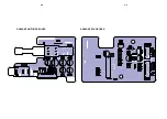
C301  A1
C302  A1
C303  A2
C304  B2
C305  A2
C306  A2
C307  A1
C308  A1
C309  B1
C310  B1
C311  B1
C312  B1
C315  A3
C316  A3
C317  A3
C318  A3
C319  A3
C321  A3
C322  A3
C323  B3
C324  B3
C325  B3
C326  B3
C327  B3
C328  B3
C329  B2
C330  B2
C331  B2
C332  B2
C333  B3
C501  C2
C502  C2
C503  C1
C504  C1
C505  C1
C506  C2
C507  C2
C508  C1
C509  C2
C510  D1
C511  B6
C512  B6
C513  D2
C514  D2
C516  D2
C517  D2
C518  C3
C522  A6
C524  B6
C525  C6
C526  C6
C527  C6
CN303   B4
COAX1  A6
CON301 A1
CON501 A5
CON502 B5
CON503 A5
CON504 C5
CON506 D5
CON507 B6
CON508 C6
CON509 B6
CON510 D6
CON512 C6
D301  A1
D302  A1
D303  A1
D304  A1
D305  A2
D306  B1
D309  A2
D310  A2
D311  B2
D312  B2
D313  B2
D314  B3
D501  C3
D502  D3
D503  B6
D504  B6
D505  C6
D506  C6
F301  A1
L301  A1
L302  A1
L303  A3

L305   B3
Q301  B2
Q302  A3
Q303  A3
Q304  B3
Q305  B2
Q306  B3
Q501  C2
Q502  C2
Q503  D1
Q504  D1
Q505  C3
Q507  C3
Q508  D3
Q509  D3
R301  A2
R302  A1
R303  A1
R304  A1
R305  A1
R306  B1
R307  B1
R308  A1
R309  B1
R310  B1
R316  A3
R317  A3
R318  B2
R319  B3
R320  B3
R321  B2
R322  B2
R323  B2
R324  B2
R325  B3
R326  B3
R327  B3
R328  B3
R501  C1
R501  C2
R502  C2
R503  C1
R504  C1
R505  C1
R506  C2
R508  C1
R509  C1
R510  C2
R511  C2
R512  C1
R513  C1
R515  D1
R516  D1
R517  D1
R518  D2
R519  D1
R520  D1
R521  D1
R522  D2
R523  C3
R524  C3
R529  A6
R530  A5
R531  C3
R532  C3
R533  C3
R534  C3
R535  D3
R536  D3
R537  D3
R538  D3
R545  C3
RV301A1
T301  A2
TR301A1
U301  A1
U303  B2
U304  B3
U304  B3
U501-1 C2
U501-2 C2
ZD301 B1
ZD302 B1
ZD303 A3
ZD304 A3
ZD305 B1

9-2

9-2

Summary of Contents for DVD590M

Page 1: ...sion of Philips Published by KC TCL 0401 Service Audio Printed in The Netherlands Subject to modification GB 3139 785 30470 DVD Player TABLE OF CONTENTS Page Technical Specifications 1 2 Safety Instruction Warnings and Notes 1 3 Mechanical and Dismantling Instruction 2 Region Code Software version and upgrades 3 Trouble Shooting Chart 4 Block diagram and Wiring diagram 5 Electrical Schematics and ...

Page 2: ... Digital multi channel sound on 2speakers Audio performance DA converter 24bits DVD fs 96kHz 4Hz 44kHz DVD SVCD fs 48kHz 4Hz 22kHz SVCD VCD CD fs 44 1kHz 4Hz 20kHz Signal Noise 1kHz 90dB Dynamic Range 1kHz 80dB Cross talk 1kHz 80dB Distortion and Noise 1kHz 80dB MPEG MP3 MPEG Audio L3 Connections Y output Cinch green Pb Cb output Cinch blue Pr Cr output Cinch red S video output Mini DIN 4pins Vide...

Page 3: ... pins of the mains plug 2 Set the mains switch the on position keep the mains cord unplug 3 Measure the resistance value between the mains plug and the front panel controls and chassis bottom 4 Repair or correct unit when the resistance measurement is less than 1MO 5 Verify this before you return the unit to the customer user ref UL standard no 1492 6 Switch the unit off and remove the wire betwee...

Page 4: ...o touch copper tracks and or components in this unshielded primary area when you service the player Service personnel must take precautions to prevent touching this area or components in this area A lighting stroke and a stripe marked printing on the printed wiring board indicate the primary side of the power supply Never replace modules or components while the unit is on 2 Laser The use of optica...

Page 5: ...0M player For item number refer to the exploded view Step1 Remove 4 screws at the Rear Cover Figure 1 Step2 Push the Top Cover toward the Rear Figure 2 Step3 Remove 5screws at the Inner Metal Plate and then open it Figure 3 Figure 1 Figure 2 Figure 3 2 pcs M C screw F3x7 5pcs Triangle M C Screw B3x6 2 1 2 pcs M C screw F3x7 ...

Page 6: ...ns Step4 Remove the metal plate the Loader and other modules will be visible Figure 4 Step5 Use a small flat tip screw driver to release the snaps on the Front Panel and gently pull the Panel out from the set Figure 4 Figure 5 2 2 Figure 5 ...

Page 7: ...llipses at both sides of the Loader and disconnect 4 wire connections as the arrowhead aim Figure 6 Figure 6 Figure 7 2 3 Figure 8 Step7 Remove the power board First remove the 5 screws that added ellipses Figure 7 secondly remove the 8 screws inside the big ellipse Figure 8 ...

Page 8: ...fier Board Echo Board Karaoke Amplifier Board Karaoke ECHO Board How to remove the disc that is jammed in the loader Firstly remove the screw on the Loader cover PUSH Secondly remove the Loader cover and push the Strap forward until the Disk come out 2 4 ...

Page 9: ...RING Add silicon glue around the two capacitors Add silicon glue on the PCB Pads 2 5 Add silicon glue C326 Add silicon glue C305 Add silicon glue cover the weld joints of Q301 R306 R304 R305 R302 Add the conductive silicon glue between the IC and the heat sink ...

Page 10: ...e control 3 The software version and other informations are display on the TV screen as follows ALI SYSTEM SETUP DATE yyyymmdd Version of application software MPEG F W xx xx x x softwareversionofMPEG MPEG H W xx xx xxx SERVO F W xxxxx software version of Servo SERVO H W xxxxx xx VENDER PHILIPS VENDER VER 590AP DISK TYPE NTSC DISABLE VCD OFF REGION CODE 3 PARENTAL CC 8 PARENTAL PW 0000 Changing the...

Page 11: ...eck if F301 Tr301 L031 D302 D303 D304 Is damaged GO NO YES YES Standby LED does not light Check point The output voltage of VCC is 5V 5 Observe If the LED can be lighted up again when the R5 on front panel Board is shot circuit manually Check point The voltage of the anode of capacitor C305 is over 150V Observe N A NO Check point The pin1 of C303 is 2 5V Observe N A NO Yes NO 4 1 ...

Page 12: ...303 is 5V Check if VA VA 2 5V are Ok Solution Replace Q302 Q303 U304 if damaged Solution Short PCON to GND and voltage output restored Replace the CPU IC on front panel Observe Check D311 Solution Replace if damaged Replace Q306 GO Stand LED Light up Not supply voltage output when press power key Check point Measure Q306 Observe BASE terminal Q306 is 0V Collection terminal of Q306 is 5V Check poin...

Page 13: ... Observe the 5V and 2 5 supply voltage are Presented Board is shot circuit manually Check point Q9 Lm117 3 3V on main board Observe the 3v3 at pin3 of Q9 Check point Measure pin112 of Ali M3351 Observe Measure the 27Mhz oscillation frequency Check point check the collector of Q1 Observe a stable 5V is presented The pin1 of C303 is 2 5V Observe N A YES NO NO YES NO YES YES NO Check points check the...

Page 14: ...t between 34 and Cn503 Solution Replace if Q6 Q7 Q4 Q5 damaged NO Audio output is normal but no Video Check point R87 RP2 RP5 RP6 On the main board Observe Is there any video output signal Board is shot circuit manually Check point L12 L11 L6 L4 L9 L7 on main board Observe open circuit Check point pin2 4 5 6 7 8 Of Cn503 on power board Observe open happen NO NO YES YES 4 4 GO CVBS R96 point wavefo...

Page 15: ...at BAS Terminal of Q12 Solution Check the IC U2 at front control board Solution Replace U20 8728 Solution Replace U501 Solution Check the power supply circuit GO YES Signal is presented NO NO Video output is normal but no analogue audio output Check point U501 at power board Observe the output voltage of U501 Check point Q507 on power board Observe the voltage presented at collector terminal of Q5...

Page 16: ...Digital output from coaxial terminal Check point the user s set up manual Observe check the audio set up is in digital output mode Check point pin 10 of CN503 on power board Observe the 5V is presented Check point R119 at pin 162 of M3351 Observe check is the R119 opened Check point J4 at main board and CX503 on power board Observe check is any poor contact between J4 and Cn5103 YES NO 4 6 ...

Page 17: ...2 Solution check if the transistor Q501 Q502 Q508 Q509 replace the faulty transistor High audio POP noise when switch ON and Check point the pin2 of CON 512 on power board Observe check the voltage switch to low when switch ON or OFF the set YES 4 7 NO GO ...

Page 18: ... connector between echo board and microphone GO NO YES NO YES YES NO NO YES YES NO No voice from Microphone Check point the Q503 on power board Observe check the collector terminal voltage is over 0v7 Check point Q503 on power board Observe check the collector terminal is short circuit to ground Check the 5V is presented Check point Microphone input Observe check if the any signal presenting at pi...

Page 19: ...ce Q503 if defected GO NO NO Cannot turn OFF the voice from Microphone Check points select karaoke on off on the setup menu Enter the setup menu to select karaoke on off and check the voltage Check points collector terminal of Q504 on power board Observe check the voltage is over 0v7 YES YES 4 9 Solution Replace the loader Can only read DVD Disc but not VCD and CD YES ...

Page 20: ...O Feedback Oscillation when switch the Microphone output Check point the pin 2 of U601 on echo board Observe check the voltage is Check point Capacitors C605 to C610 at U601 Observe check if there is any poor soldering or short circuit Check point capacitors C602 to C604 at U601 Observe check if there is any poor soldering or short circuit 4 10 ...

Page 21: ...NC SPDIF 1 10 R GND L DMUTE 1 4 4 1 1 5 PCON FMUTE VCC GND 5V IR GND POWEROFF 1 6 VA VA GND MIC 5V 1 7 VA VA NC GND MICAMPOUT MIC1 MIC2 ALI3351 ALIM5709 BA6849 BA5954 AM29F040 2 32MSDRAM 74HC373 WM8728 TEA1523P PC123Y TL431 NJM4558 PT2399 NJM4558 KARAOKE AMP BOARD KARAOKE ECHO BOARD POWER AV BOARD SERVO DECODER BOARD FRONT BOARD REMOTE LOADER MECHANISM PIC16C54 S0122 74HC86 REM For Karaoke version...

Page 22: ...ODULE It is not recommended for component repair on this module but to replace the entire assembly when it becomes defective The complete Loader Module is available under service part code 9965 000 22493 For information only 6 1 6 1 ...

Page 23: ... VPA RFAC BYP DIN DIP FNP FNN VNA MEV RX SDEN SDATA SCLK V33 LCP LCN MNTR CE FE TE PI V25 V125 TPH DFT LINK R45 33K R109 51 C51 0 1U TP32 SBAD R110 220 R37 100 R42 10K R107 47K BC29 0 1U D4 1N4148 R54 1K R106 47K R36 12K 1 J12 INCON AC 4PIN 2 0mm 1 2 3 4 C42 0 1U C57 100P Q2 2SB1132 TP27 LINK L1 10UH 0805 R55 1 0805 R38 100 C39 470P R58 1 0805 R39 1 2K R56 1 0805 BC26 0 1U R46 22K C38 0 01U BC33 0...

Page 24: ...8 29 30 31 32 33 34 35 36 37 38 39 40 41 42 43 44 45 46 47 48 49 50 51 52 53 54 55 56 57 58 59 60 61 62 63 64 65 66 67 68 69 70 71 72 73 74 75 76 77 78 79 80 81 82 83 84 85 86 87 88 89 90 91 92 93 94 95 96 97 98 99 100 101 102 103 104 105 106 107 108 109 110 111 112 113 114 115 116 117 118 119 120 121 122 123 124 125 126 127 128 129 130 131 132 133 134 135 136 137 138 139 140 141 142 143 144 145 1...

Page 25: ... 7ns TSOP 1 2 3 4 5 6 7 8 9 10 11 12 13 14 15 16 17 18 19 20 21 22 23 24 25 26 27 28 29 30 31 32 33 34 35 36 37 38 39 40 41 42 43 44 45 46 47 48 49 50 51 52 53 54 55 56 57 58 59 60 61 62 63 64 65 66 67 68 69 70 71 72 73 74 75 76 77 78 79 80 81 82 83 84 85 86 VDD DQ0 VDDQ DQ1 DQ2 VSSQ DQ3 DQ4 VDDQ DQ5 DQ6 VSSQ DQ7 NC VDD DQM0 WE CAS RAS CS NC BA0 BA1 A10 AP A0 A1 A2 DQM2 VDD NC DQ16 VSSQ DQ17 DQ18 ...

Page 26: ... 1 2 3 4 5 6 7 8 9 10 L31 FB 0603 R94 51 J3 SCART VGA CON 8PIN 2 0mm 1 2 3 4 5 6 7 8 R69 47 R120 47 U11 WM8746 1 11 12 13 14 9 8 10 2 3 4 5 6 7 15 28 20 24 26 22 18 27 25 23 21 19 17 16 DVDD DGND LATCH 12S SCLK IWL SDIN DM0 MUTE MODE LRCLK2 MCLK BCLK LRCLK DIN0 DIN1 DIN2 AVDD1 AVDD2 AGND1 AGND2 GR0 GR1 GR2 OUT0R OUT0L OUT1R OUT1L OUT2R OUT2L CAP L38 FB 0603 TC12 100U 10V R129 0 J14 MIC CON 3PIN 2 ...

Page 27: ...V VD25D TV GND 12V 5V 5V VD33D AD5V 12V A GND VD25D VD33D TC22 100U 10V TC15 100U 10V BC62 0 1U U12 78M05CDT 1 2 3 OUT GND IN BC55 0 1U J15 POWER CON 6PIN 2 54mm 1 2 3 4 5 6 TC26 100U 10V BC66 0 1U TC18 220U 10V TC25 100U 16V L15 FB 0805 TC19 100U 10V BC59 0 1U R97 3 3 0805 BC58 0 1U L17 FB 0805 TC16 100U 10V L18 1UH 0805 TC23 100U 10V BC56 0 1U D7 OPEN TC17 100U 10V Q8 L1117 2 5V 1A TO252 3 2 1 I...

Page 28: ...TABLE OF CONTENTS Front Board Circuit Diagram 7 2 Front Board Component Chip Layout 7 3 Electrical Parts List 7 4 FRONT BOARD 7 1 ...

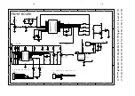
Page 29: ...2 PIC16C54S 1 2 3 4 5 6 7 8 9 10 11 12 13 14 15 16 17 18 RA2 RA3 T0CKI MCLR Vss RB0 RB1 RB2 RB3 RB4 RB5 RB6 RB7 Vdd OSC2 OSC1 RA0 RA1 U1 S0102 1 2 3 4 5 6 7 8 9 10 11 12 24 23 22 21 20 19 18 17 16 15 14 13 KI2 KI3 KI4 KI5 KI6 KI7 REM VDD SEL OSCO OSCI VSS KI1 KI0 CCS KI O0 KI O1 KI O2 KI O3 KI O4 KI O5 KI O6 KI O7 LMP C10 47u 10v R13 33R LD3 standby 1 2 CON1 PITDH 2 0 6 1 2 3 4 5 6 R2 4K7 R20 10R ...

Page 30: ...FRONT BOARD Top Side 7 3 7 3 FRONT BOARD Bottom Side ...

Page 31: ...65 000 14026 CAP ELEC 10UF 16V 20 SMALL C15 9965 000 22464 ELCAP 47UF 16V 20 SMALL DIODES D1 4822 130 81637 PMLL4148L D2 4822 130 81637 PMLL4148L D3 4822 130 81637 PMLL4148L LD1 9965 000 22465 LED BT 402YOEN 30 605B LD2 9965 000 22465 LED BT 402YOEN 30 605B LD3 9965 000 20399 LED RED HFR103 3MM TRANSISTORS Q1 9965 000 20152 MMBT3904LT1 SMD SOT23 Q2 9965 000 20152 MMBT3904LT1 SMD SOT23 Q3 9965 000 ...

Page 32: ... Karaoke Board Circuit Diagram 8 2 ECHO Board Circuit Diagram 8 3 Karaoke Amplifier ECHO Board Component Chip Layout 8 4 Electrical Parts List 8 5 TABLE OF CONTENTS KARAOKE AMPLIFIER ECHO BOARD 8 1 ...

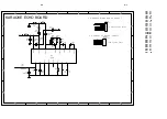
Page 33: ...7 47K U401B 4558 5 6 7 8 4 C402 22UF 16V R404 1K U401A 4558 3 2 1 8 4 R406 1K R403 47K C408 22UF 16V C404 104 R402 1 2K CN401 PITCH 2 0 7 3 4 5 6 7 2 1 3 4 5 6 7 2 1 C406 104 C407 101 MIC401 1 2 3 1 2 3 RP401 10K C411 1uF 16V C405 100UF 25V C401 A2 C402 B3 C404 B3 C405 A3 C406 A3 C407 B3 C408 D2 C409 C2 C410 A3 C411 C2 CN401 C4 MIC401 A1 R401 A2 R402 B3 R403 B3 R404 C2 R405 C2 R406 C2 R407 A2 R408...

Page 34: ... 10K R603 12k C601 4 7UF 50V R608 10K C608 104 C612 100UF 16V C606 683 C605 683 CON602 PITCH 2 0 5 1 2 3 4 5 1 2 3 4 5 C613 4 7UF 50V U601 PT2399 1 2 3 4 5 6 7 8 9 10 11 12 13 14 15 16 VCC REF AGND DGND CLK O VCO CC1 CC0 OP1 OUT OP1 IN OP2 IN OP2 OUT LPF2 IN LPF2 OUT LPF1 OUT LPF1 IN CON601 PITCH 2 0 7 3 4 5 6 7 2 1 3 4 5 6 7 2 1 R605 10K C601 A3 C602 B2 C603 B3 c604 A1 C605 B3 C606 B4 C607 B2 C60...

Page 35: ...KARAOKE ECHO BOARD 8 4 KARAOKE AMPLIFIER BOARD 8 4 ...

Page 36: ...TORS C403 4822 124 40207 100UF20 25V C405 4822 124 40207 100UF20 25V RESISTORS RP401 9965 000 14035 POTM ROT WH09GTX 1C B10K F25 COILS FILTERS L601 9965 000 14082 COIL CHOKE 10UH 10 INTEGRATED CIRCUITS U401 9965 000 14591 IC RC4558DR U601 4822 209 17186 PT2399 Note Only the parts mentioned in this list are normal service spare parts ...

Page 37: ... Power AV Board Circuit Diagram 9 2 Power AV Board Component Layout 9 3 Electrical Parts List 9 4 TABLE OF CONTENTS POWER AV BOARD 9 1 ...

Page 38: ...H C302 NU C507 102 U302 PC123Y 1 2 4 3 R532 10K L305 10uH C325 0 1uF R509 10K R308 680k PAS R534 100K CON503 PITCH 2 0 10 1 2 3 4 5 6 7 8 9 10 R510 470R R536 10K D303 1N4007 R506 470R R503 10K C322 100uF 25V R319 330 1 4W C527 330P R301 100K 2W R504 3K3 R518 68R Q302 8550 C303 223 400V CON506 PITCH 2 0 12 1 2 3 4 5 6 7 8 9 10 11 12 C518 470uF 16V C320 470uF 16V D502 IN4148 C321 0 1uF Q502 C9014 1 ...

Page 39: ...POWER AV BOARD 9 3 9 3 ...

Page 40: ...00 20424 COIL CHOKE 3 3 UH 10 L304 9965 000 20425 COIL CHOKE SG9006 10UH 20 L305 9965 000 20425 COIL CHOKE SG9006 10UH 20 DIODES D301 4822 130 30799 1N4007G D302 4822 130 30799 1N4007G D303 4822 130 30799 1N4007G D304 4822 130 30799 1N4007G D305 9965 000 20421 DIODE 1H8 D306 3141 018 51230 DIO REC FR104 D309 3141 018 51230 DIO REC FR104 D310 4822 130 82936 RU3YX D311 9965 000 14601 DIODE 31DQ06 D3...

Page 41: ...MAIN ENCASING EXPLODED VIEW 10 1 ...

Page 42: ...BBER PAD 2 19 9965 000 22486 TOP COVER PALSTIC 23 9965 000 22488 BACK PLATE 27 9965 000 13933 POWER CORD 1880 20MM 28 9965 000 13941 MIC KNOB 34 9965 000 22489 BRACKET 35 9965 000 22487 LOWER COVER 36 9965 000 22492 RUBBER PAD 3 A_CBL 9965 000 22497 AUDIO CABLE 1 5M WHITE RED IFU 9965 000 22498 OPERATION MANUAL IFU RC 9965 000 21425 REMOTE CONTROLLER V_CBL 9965 000 22495 VIDEO CABLE 1 5M YEL Note ...

Page 43: ...Version 1 0 Initial release REVISION LIST 11 1 ...

Reviews: