Directions For Use
3.
16
4
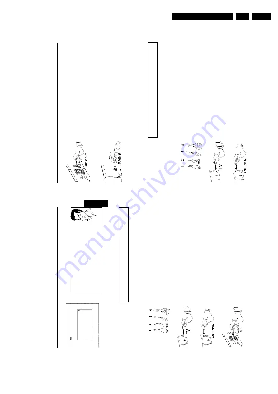
Insert
one
end
of
the
supplied
audio
(Cinch)
cable
into
the
red/white
Cinch
socket
OUT
L
AUDIO
R
at
the
back
of
the
DVD
recorder
and
the
other
end
into
the
audio
input
socket
(usually
red/white)
on
the
TV
set
(usually
labelled
'Audio
in'
or
'AV
in'.
See
TV
operating
instructions).
5
Switch
on
the
TV
set.
Switch
the
TV
set
over
to
the
SVHS
input
socket
or
select
the
relevant
programme
number.
Please
see
your
TV's
operating
instructions
for
the
programme
number
you
need.
6
Insert
one
end
of
the
supplied
mains
cable
into
the
mains
socket
4
MAINS
at
the
back
of
the
DVD
recorder
and
the
other
end
into
the
wall
socket.
The
most
important
features
of
the
DVD
recorder
will
appear
in
scrolling
text
on
the
display.
After
the
first
installation
is
completed
this
function
will
be
switched
off.
How
you
switch
on
this
function
again,
read
in
the
chapter
'User
preferences'
in
the
section
'standby'.
7
Switch
on
the
DVD
recorder
using
STANDBY/ON
m
.
IS
TV
ON?
'
will
appear
on
the
display.
Then,
read
the
paragraph
on
'Initial
installation'
in
'Installing
your
DVD
recorder'.
Connecting
with
video(CVBS)
cable
This
cable,
usually
with
yellow
Cinch
connectors,
is
used
for
transmitting
the
Composite
Video
signal
(FBAS,
CVBS).
In
this
method
of
transmission
the
colour
signal
and
the
brightness
signal
are
transmitted
on
the
same
cable.
In
certain
circumstances,
this
can
lead
to
problems
with
the
picturem,
such
as
'Moiré'
patterns.
Have
the
following
cables
ready:
an
aerial
cable
(1,
supplied),
a
mains
cable
(2,
supplied),
a
video
(CVBS)cable
(3,
supplied,
yellow
plug),
an
audio
cable
(4,
supplied,
red/white
plug).
1
Remove
the
aerial
cable
plug
from
your
TV
set.
Insert
it
into
the
ANTENNA
IN
socket
at
the
back
of
the
DVD
recorder.
2
Insert
one
end
of
the
supplied
aerial
cable
into
the
TV
OUT
socket
at
the
back
of
the
DVD
recorder
and
the
other
end
into
the
aerial
input
socket
at
the
back
of
the
TV
set.
Connecting
the
DVD
recorder
15
Virgin
mode
Menu
Language
English
Español
Français
Italiano
Deutsch
Press
OK
to
continue
a
My
screen
is
empty.
b
Many
TV
sets
are
switched
by
the
DVD
recorder
to
the
programme
number
for
the
scart
socket
by
way
of
a
control
signal
sent
through
the
scart
cable.
b
If
the
TV
set
does
not
automatically
switch
to
the
scart
socket
programme
number,
manually
change
to
the
corresponding
programme
number
on
your
TV
set
(see
your
TV's
operating
instructions).
b
Check
that
the
scart
cable
is
connected
from
the
TV
set
to
the
EXT
1
TO
TV-I/O
socket
on
the
DVD
recorder.
The
EXT
2
AUX-I/O
socket
is
intended
only
for
additional
devices.
Problem
Then,
read
the
paragraph
on
'Initial
installation'
in
'Installing
your
DVD
recorder'.
Connecting
with
an
SVideo(Y/C)cable
This
connecting
cable,
also
known
as
the
SVHS
cable,
is
used
to
transmit
the
brightness
signal
(Y
signal)
and
colour
signal
(C
signal)
separately.
This
mini
DIN
socket/plug
is
also
called
a
Hosiden
socket/plug.
Have
the
following
cables
ready:
an
aerial
cable
(1,
supplied),
a
mains
cable
(2,
supplied),
an
S-Video(SVHS)
cable
(3),
an
audio
cable
(4,
supplied,
red/white
plug).
1
Remove
the
aerial
cable
plug
from
your
TV
set.
Insert
it
into
the
ANTENNA
IN
socket
at
the
back
of
the
DVD
recorder.
2
Insert
one
end
of
the
supplied
aerial
cable
into
the
TV
OUT
socket
at
the
back
of
the
DVD
recorder
and
the
other
end
into
the
aerial
input
socket
at
the
back
of
the
TV
set.
3
Insert
one
end
of
an
S-Video(SVHS)
cable
into
the
OUT
S-VIDEO
(Y/C)
socket
at
the
back
of
the
DVD
recorder
and
the
other
end
into
the
S-Video
(SVHS)
input
socket
on
the
TV
set
(usually
labelled
'S-Video
in'
or
'SVHS
in'.
See
TV
operating
instructions).
ENGLISH
Connecting
the
DVD
recorder
Summary of Contents for DVDR70/001
Page 88: ...Diagnostic Software EN 88 DVDR70 DVDR75 0x1 5 ...
Page 138: ...EN 138 DVDR70 DVDR75 0x1 7 Circuit Diagrams and PWB Layouts Layout DVIO Board Part 1 Top View ...
Page 139: ...Circuit Diagrams and PWB Layouts EN 139 DVDR70 DVDR75 0x1 7 Layout DVIO Board Part 2 Top View ...
Page 166: ...EN 166 DVDR70 DVDR75 0x1 7 Circuit Diagrams and PWB Layouts ...
Page 194: ...Circuit IC descriptions and list of abbreviations EN 194 DVDR70 DVDR75 0x1 9 Figure 9 15 ...
Page 195: ...Circuit IC descriptions and list of abbreviations EN 195 DVDR70 DVDR75 0x1 9 Figure 9 16 ...
Page 220: ...Circuit IC descriptions and list of abbreviations EN 220 DVDR70 DVDR75 0x1 9 ...
Page 221: ...Circuit IC descriptions and list of abbreviations EN 221 DVDR70 DVDR75 0x1 9 ...
Page 223: ...Circuit IC descriptions and list of abbreviations EN 223 DVDR70 DVDR75 0x1 9 ...
Page 224: ...Circuit IC descriptions and list of abbreviations EN 224 DVDR70 DVDR75 0x1 9 ...
Page 225: ...Circuit IC descriptions and list of abbreviations EN 225 DVDR70 DVDR75 0x1 9 ...
Page 226: ...Circuit IC descriptions and list of abbreviations EN 226 DVDR70 DVDR75 0x1 9 ...
Page 227: ...Circuit IC descriptions and list of abbreviations EN 227 DVDR70 DVDR75 0x1 9 ...
Page 228: ...Circuit IC descriptions and list of abbreviations EN 228 DVDR70 DVDR75 0x1 9 ...
Page 229: ...Circuit IC descriptions and list of abbreviations EN 229 DVDR70 DVDR75 0x1 9 ...
Page 231: ...Circuit IC descriptions and list of abbreviations EN 231 DVDR70 DVDR75 0x1 9 ...
Page 232: ...Circuit IC descriptions and list of abbreviations EN 232 DVDR70 DVDR75 0x1 9 ...
Page 233: ...Circuit IC descriptions and list of abbreviations EN 233 DVDR70 DVDR75 0x1 9 ...
Page 235: ...Circuit IC descriptions and list of abbreviations EN 235 DVDR70 DVDR75 0x1 9 ...
Page 237: ...Circuit IC descriptions and list of abbreviations EN 237 DVDR70 DVDR75 0x1 9 ...
Page 238: ...Circuit IC descriptions and list of abbreviations EN 238 DVDR70 DVDR75 0x1 9 ...


