Mechanical Instructions
EN 46
DVDR880-890 /0X1
4.
4.1.4
Analog board
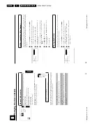
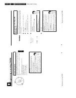
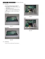
To put the analog board in service position, demount the
assembly of analog board and backplate as follows:
1.
Remove the screw from the backplate to the mains inlet of
the power supply
2.
Remove the screw safety holder
3.
Remove the 3 screws of the analog board to the frame
4.
Release the snap of the spacer of the analog board to the
frame.
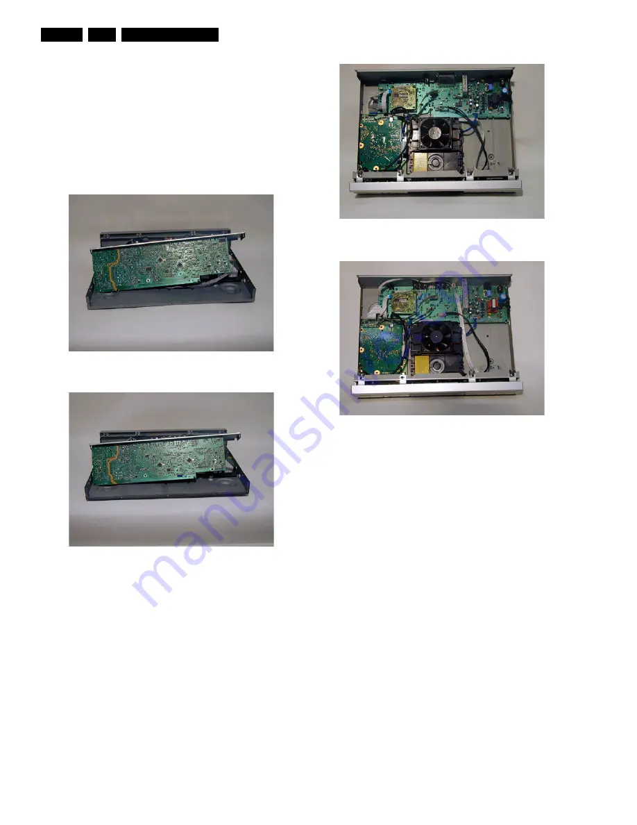
Turn the assembly of the back plate and the analog board
against the loader.
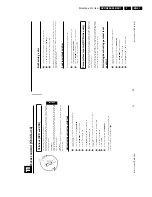
Analog Europe
Figure 4-7
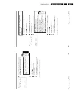
Analog NAFTA
Figure 4-8
4.1.5
Cable Routing
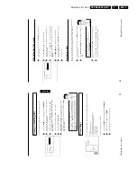
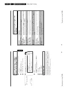
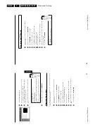
Take care of the correct cable routing. See pictures below.
Europe
Figure 4-9
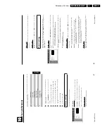
NAFTA
Figure 4-10
Summary of Contents for DVDR880/001
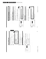
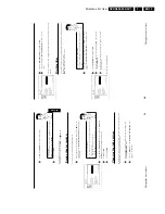
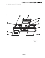
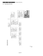
Page 48: ...Mechanical Instructions EN 50 DVDR880 890 0X1 4 4 5 Dismantling Instructions Figure 4 14 ...
Page 166: ...Circuit IC Descriptions and List of Abbreviations EN 168 DVDR880 890 0X1 9 ...
Page 167: ...Circuit IC Descriptions and List of Abbreviations EN 169 DVDR880 890 0X1 9 ...
Page 174: ...Circuit IC Descriptions and List of Abbreviations EN 176 DVDR880 890 0X1 9 IC7411 ...
Page 182: ...Circuit IC Descriptions and List of Abbreviations EN 184 DVDR880 890 0X1 9 ...
Page 183: ...Circuit IC Descriptions and List of Abbreviations EN 185 DVDR880 890 0X1 9 ...
Page 184: ...Circuit IC Descriptions and List of Abbreviations EN 186 DVDR880 890 0X1 9 ...
Page 203: ...Circuit IC Descriptions and List of Abbreviations EN 205 DVDR880 890 0X1 9 ...

