3-3
Mechanical and Dismantling Instructions
Dismantling Instruction
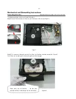
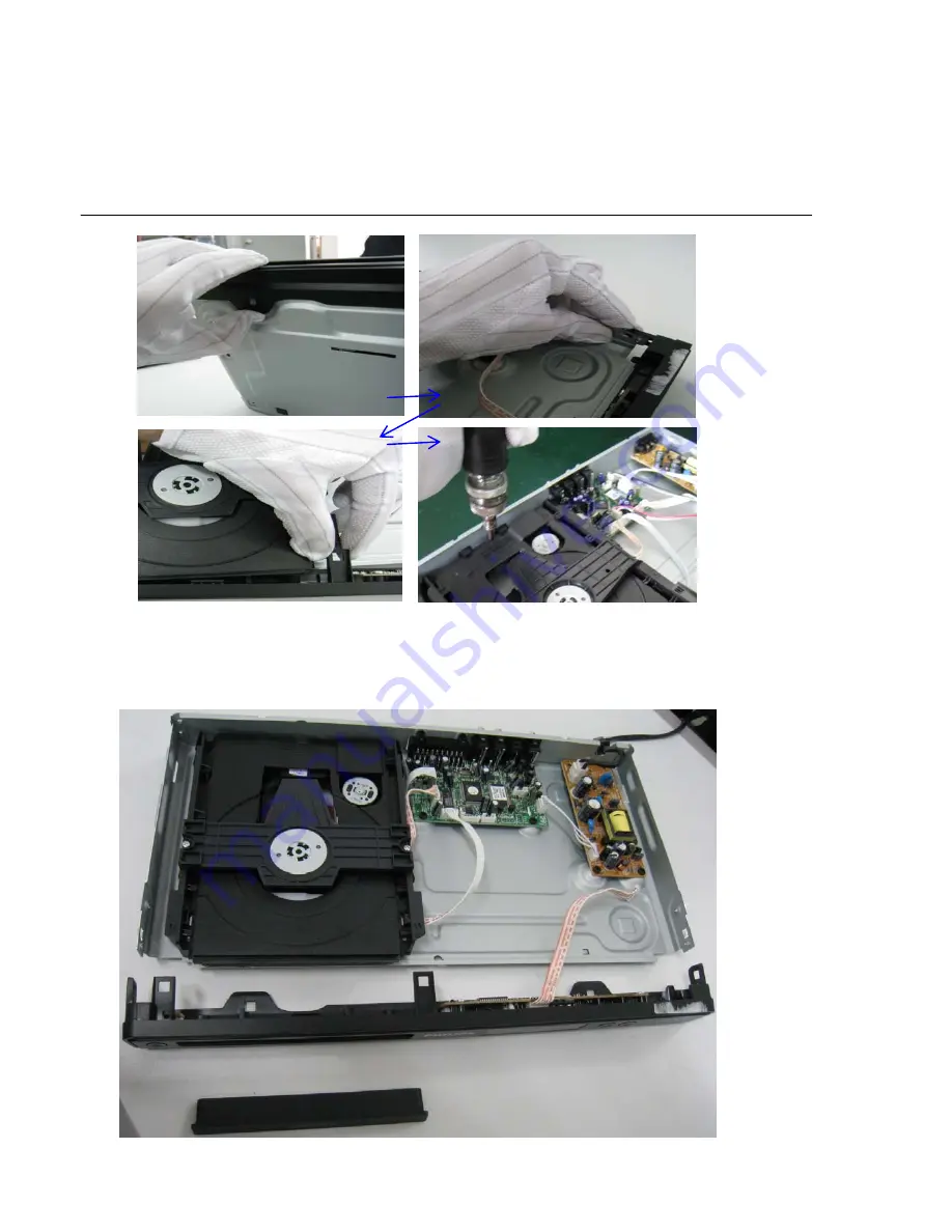
Figure 5
Step5
: Dismantling Loader, disconnect the 3 connectors (XP7, XP8, XP9 ) aiming in the below figure, and remove 1 screw that
connects the loader and the bottom cabinet. (Figure 5 & 6)
Figure 6
Detailed information please refer to the model set.
Summary of Contents for DVP3320
Page 32: ...Front Board Switch Board Print layout Bottom side 7 9 7 9 ...
Page 33: ...OK Board Print layout Top side OK Board Print layout Bottom side 7 10 7 10 ...
Page 34: ...Power Board Print layout Bottom side 7 11 7 11 ...
Page 35: ...Main Board Print layout Top side 7 12 7 12 ...
Page 36: ...Main Board Print layout Bottom side 7 13 7 13 ...
Page 39: ...REVISION LIST Version 1 0 Initial release for DVP3320 55 9 1 ...


