product specifications:
Supply:
100-240V 50/60Hz Single Phase at 0.25A
Control Output:
Mains Output:
1 x DALI Control Output, supporting one full DALI universe of 64 channels, including backward channel and multi
master communication to Philips Dynalite user interfaces.
1 x 20 Amp feed thru switched circuit for DALI ballast mains supply
Supply Terminals:
1 x Phase, 1 x Neutral, 1 x Earth, 1 x 4mm
2
max conductor size
Output Terminals:
1 x Ballast power circuit
– Line in, Line out, Loop, Loop - 1 x 4mm
2
max conductor size
1 x DALI Ballast circuit - DA-, DA+ - 1 x 4mm
2
max conductor size
Control Inputs:
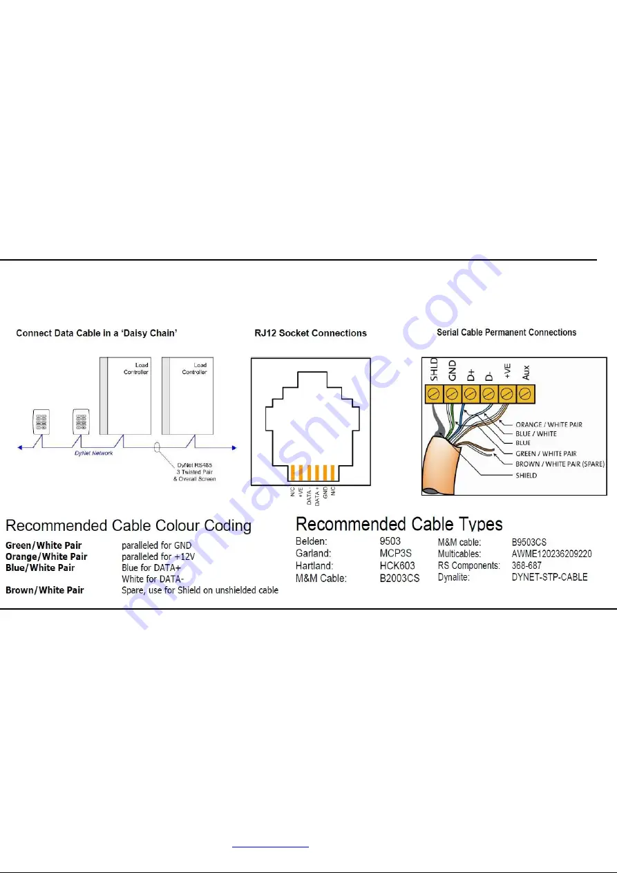
1 x RS485 DyNet serial port consisting of 1 x RJ12 socket & 1 x 5 way terminal block
1 x AUX dry contact input and ground
DALI BUS DC Supply:
Inbuilt, Rated 220mA @ 16VDC current unit max 250mA
DyNet DC Supply:
120mA (capacity for approximately 6 panels)
Preset Scenes:
170
Compliance:
CE, C-Tick
Operating Environment:
0° to 40°C ambient temperature
0% to 90% RH non-condensing
Construction:
Polycarbonate DIN rail mount
Dimensions:
H 93 mm x W 105mm x D 75mm
Weight:
0.45kg
DDBC120-DALI Instruction Manual Rev B.doc.
Specifications subject to change without notice.
Philips Dynalite manufactured by WMGD Pty Ltd (ABN 33 097 246 921) Unit 6, 691 Gardeners Road Mascot NSW 2020 Australia Tel: +61 2 8338 9899 Fax: +61 2 8338 9333
installation steps
Isolate Mains supply, DALI and Dynet bus prior to wiring
1.
Mount the device on a DIN rail inside an approved enclosure.
2.
Connect single phase supply and earth to units supply terminals: This is required for the units operation.
3.
Calculate total loading of the lighting to ensure the switched output is not overloaded. The maximum loading of this device shall not exceed 20A.
Ensure load in rush current does not exceed 500A, de-rating for electronic loads may apply. Then connect load cables between the
“
OUT
” and
“
LOOP
” terminals.
4.
Connect 20A active supply between
“
IN
” & “
LOOP
” terminals. Supply must be protected by a 20A circuit breaker maximum.
5.
Connect the DALI bus cables to
“
DA+
” and “
DA-
“: Use a mains rated 2 core cable to connect the DALI bus to the DALI ports on all DALI
devices. The DALI bus cable should not be longer than 300 Metres, and should have a minimum cross section area based on cable length as
follows:
- Up to 100 Metres: 0.5mm
2
- 100 to 150 Metres: 0.75mm
2
- 150 to 300 Metres: 1.5mm
2
The DALI bus is not SELV and must be treated as a mains cable. DALI is not polarity conscious. A maximum of 64 DALI devices plus a 10
Philips Dynalite user interfaces devices (DPMI940-DALI & DUS804C-DALI) can be connected together in a DALI network.
6.
Connect Dynet data cables to the device as per diagrams below. Ensure segregate between data cables and mains powered cables.
7.
If the Auxiliary input is to be used, connect a dry contact device in between the AUX and GND terminals. Keep cable runs between the AUX
terminals and the dry contacts under two metres. Function of the Auxiliary input will need to be programmed at the time of commissioning.
8.
Re check all terminated cables and once safe power the unit on. Correct termination of the DALI ballasts can be verified by pushing the service
switch 4 times. This will invoke a light chase, where all the correctly terminated ballasts will cycle between 100% for 3 seconds, 40% for 3
seconds and 0% for 3 seconds. This chase will repeat for 5 minutes after which all ballasts will return to their original state when first powered.
Connecting Dynet Data Cable


