background image

applications 

DNG485 Instruction Manual Rev F.doc   

4


The DNG485 can be used for several different applications, some of which are described below: 


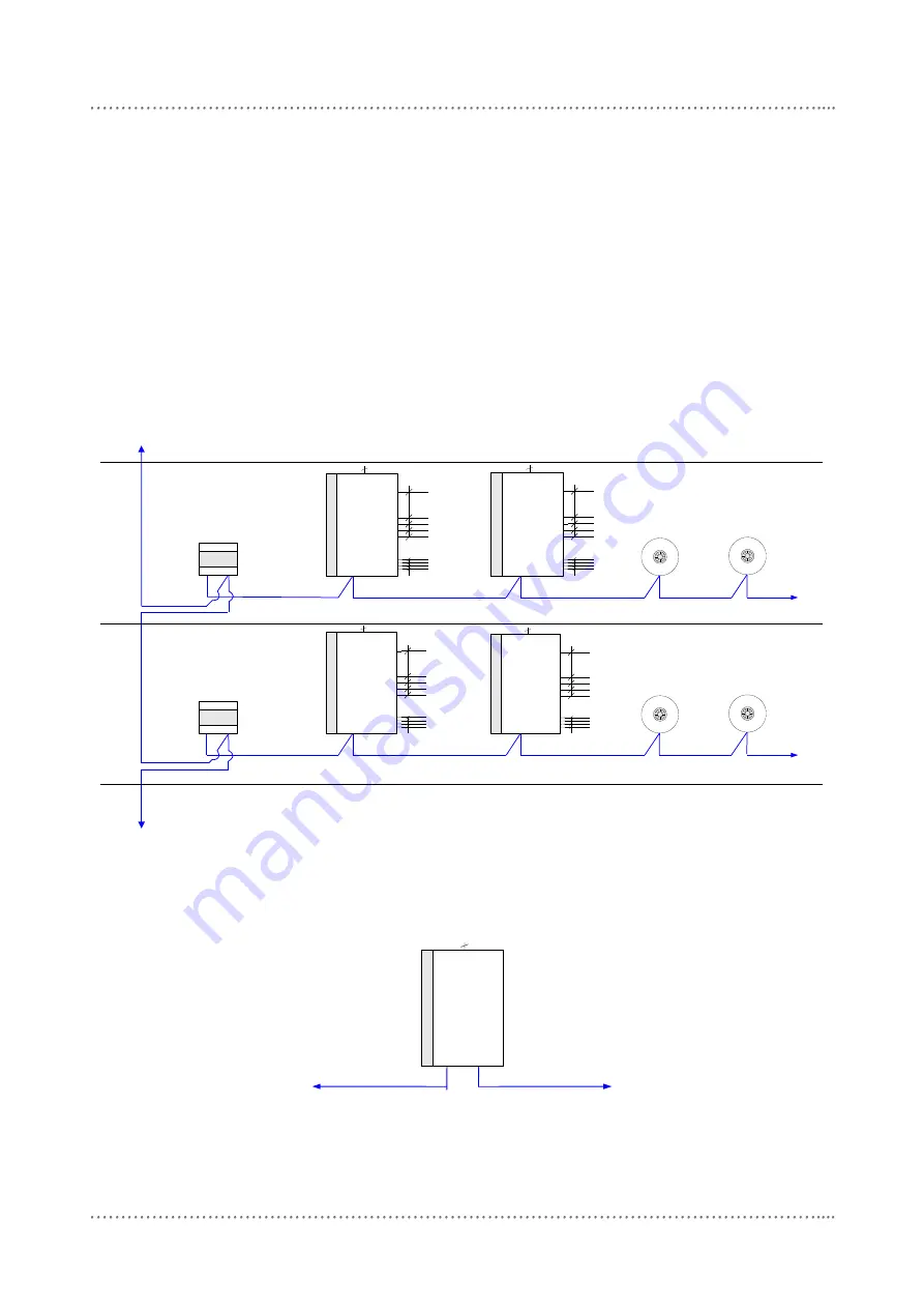
Implementing Trunk/Spur Topology 

This style of topology is used in large installations, where there is one or more data trunk cables 
that may interconnect DNG485s located at different floors or distribution boards.  The other port on 
the DNG485 is then connected to a spur that feeds the dimmers and control panels in that locale.  
The recommended method of connection is to connect the Spur to the Port 1, and the trunk to the 
Port 2.  Some reasons for implementing Trunk/Spur topology include: 

OPTICAL ISOLATION 

– A fault on a Spur will be localised to that Spur only, the rest of the system 

will be unaffected. 

QUANTITY OF NETWORK DEVICES 

– A finite number of devices can be connected to a single 

RS485 data cable.  The recommended maximum number of devices i

s 128.  The use of DNG485‟s 

gives a maximum of 128 devices per spur, with 128 spurs per trunk, a total of 16384 devices per 
trunk.  There can be as many trunks as required. 


DUS703C

Universal Sensor

D

y

N

e

T

ru

n

k

DyNet Spur

DUS703C

Universal Sensor

To up to 123 more devices

DUS703C

DDNG485

Network Gateway

Universal Sensor

D

y

N

e

T

ru

n

k

DyNet Spur

DUS703C

Universal Sensor

To up to 123 more devices

To other

floors

To other

floors

DBC410

CH4

CH3

CH2

CH1

CH1
CH2
CH3
CH4

EL1

DBC410

CH4

CH3

CH2

CH1

CH1
CH2
CH3
CH4

EL1

DBC410

CH4

CH3

CH2

CH1

CH1
CH2
CH3
CH4

EL1

DBC410

CH4

CH3

CH2

CH1

CH1
CH2
CH3
CH4

EL1

DDNG485

Network Gateway

DDNG485

DDNG485

DDNG485

1

2

1

2


Interfacing To Other Systems  

The DNG485 can be used to connect other manufacturers equipment to the Dynalite network.  A 
common example of this is converting DMX512 into DyNet. When setting up the DMX512 network 
ensure  that  it  is  connected  to  Port  2  of  the  DNG485  and  that  both  ends  of  the  DMX  cable  are 
terminated with 120

Ω resistors. 


DyNet DC Power Supply 

The DNG485 has a 450mA power supply on Port 1 which will supplement the DyNet power supply 
available for use by other peripherals. 

DyNet Network


DNG485


DMX512 Network


Summary of Contents for dynalite DNG485

Page 1: ...8 9899 f 61 2 8338 9333 dynalite info philips com Philips com dynalite DNG485 Network Bridge Installation Manual contents Warning 2 Mounting Supply Cable Connections 5 Features 2 Connecting Serial Control Cables 6 Important Safeguards 2 Troubleshooting 7 Internal View 3 Specifications 8 Applications for the DNG485 4 ...

Page 2: ...contact your local agent for details You should have all terminations made and be able to turn all lighting circuits on and off from control plates before the programming engineer arrives at the job Check Connections Treat this device as a switchboard that has been shipped Tighten all screw connections as vibrations from transport can cause MCB and terminal block screws to become loose Power Sourc...

Page 3: ... Enable Easy Cable Access 230V Supply Connections Knock Out For Low Voltage Cable Entry Glands for Cables 225mm 320mm Port 2 DyNet DMX Network Connections Mounting Point Port 2 Network Socket Service Switch EARTH LINK Depth 75mm N L Accessory Socket Port 1 DyNet Network Connections ...

Page 4: ...um of 128 devices per spur with 128 spurs per trunk a total of 16384 devices per trunk There can be as many trunks as required DUS703C Universal Sensor DyNet Trunk DyNet Spur DUS703C Universal Sensor To up to 123 more devices DUS703C DDNG485 Network Gateway Universal Sensor DyNet Trunk DyNet Spur DUS703C Universal Sensor To up to 123 more devices To other floors To other floors DBC410 CH4 CH3 CH2 ...

Page 5: ... accommodate 4 fixing screws up to 8mm diameter The DNG485 can be fixed to the wall without opening the cabinet or removing covers Make sure no dust or other debris enters the device during installation Do not leave the front cover off for any length of time Excessive dust and dirt can degrade internal components Allow For Cable Entry Supply cables enter the enclosure at the top If these cables ar...

Page 6: ...the Shield terminal The colour coding scheme used is not critical as long as the same scheme is used throughout the installation Serial Cable Connecting Method The recommended connecting method is to daisy chain devices ie starting at the first device then looping in then out of devices with a single cable terminating at the last device There should not be any spurs or stubs and only the first and...

Page 7: ...tivity Power supply indicator LED on PCB not lit Incorrect connection of Mains supply or no power available Check power supply to DNG485 Check Line and Neutral input connections Check Fuse if fitted Power supply indicator LED lit but no Service LED activity Supply voltage too low short circuit on network or short circuit on analogue inputs Control PCB faulty Check 5V 12V terminal voltages Disconne...

Page 8: ...evice the Service LED will blink rapidly at approximately 5 duty for a few seconds and then revert to normal Service Switch The Service Switch when pressed causes a sign on message to be transmitted onto the network If the transmission is successful the Service LED will indicate network activity detected The Sign on message contains information about the device such as box number device type and e...

Reviews: