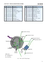
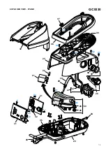
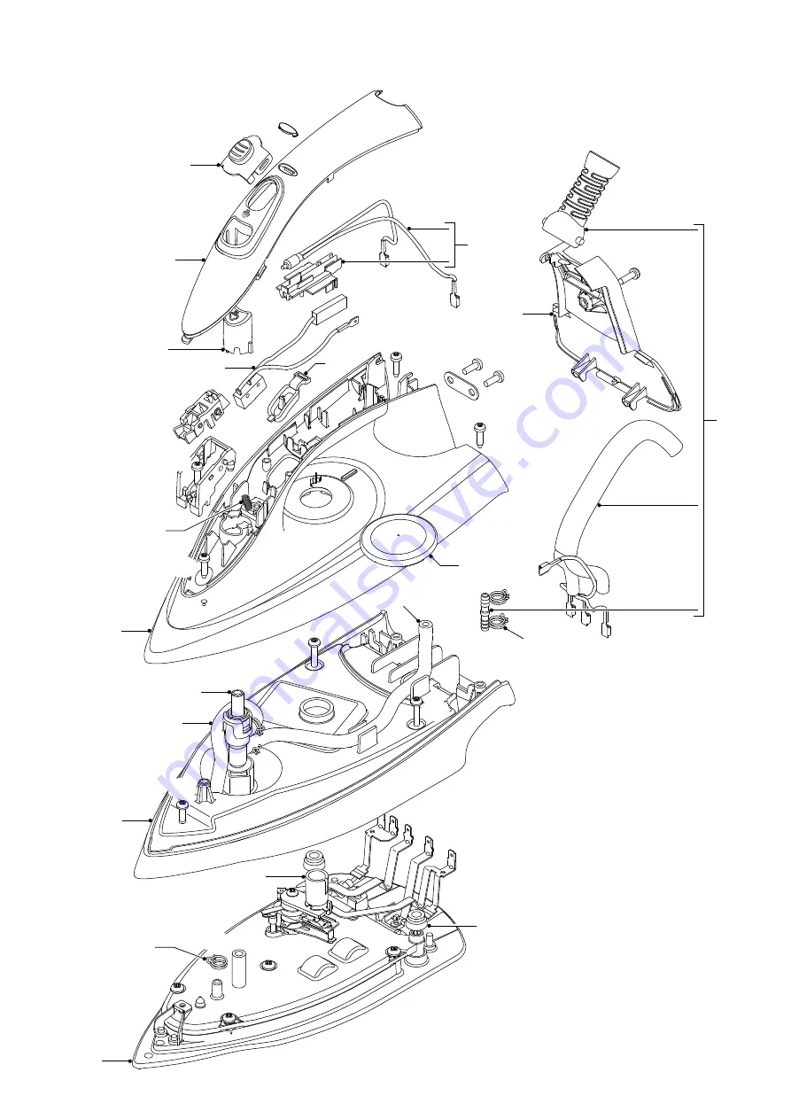
background image

GC8330

4-8

EXPLODED VIEW - IRON

13

14

4

17

18

16

11

10

6

7

2

9

1

3

8

19

12

15

5

A

S

N

L

E

B1

B2

D3

Hose
clip (a)

Hose
clip (b)

E2

D2

C

D1

E1

E3

4

Summary of Contents for EasyCare GC8330

Page 1: ... TV After the product has been repaired it should function properly and has to meet the safety requirements as officially laid down as this moment TECHNICAL INFORMATION Voltage 220 240 V Frequency 50 60 Hz Power Iron 800 W Boiler 1370 W Dimension F box 350 x 350 x 250 mm L x W x H Weight with packing 6 4 kg Water advice If the tap water in your area is very hard it is advisable to mix the tap wate...

Page 2: ...p assy N S Fig 2 Wiring at rear HOUSING Part 2 DISASSEMBLY ADVICE IRON INLAY 17 STEAM LOCK 13 LAMP MOUNTED ASSY 8 MICROSWITCH ASSY 11 TRIGGER 12 THERMOSTAT DIAL ASSY 15 HOUSING PRINTED 10 SOLEPLATE COVER 6 THERMOSTAT BUSH 9 RUBBER HOSE 3 SOLEPLATE ASSY 1 Remove Screw A Disassemble BACKPLATE 18 Release Inlay rear catch Disassemble INLAY 17 Disassemble STEAM LOCK 13 Disassemble MICROSWITCH ASSY 11 R...

Page 3: ...8 19 4239 021 41330 4239 015 56120 4239 015 56510 4239 010 10110 4239 015 70150 4239 026 42271 4239 021 31780 4239 021 36861 4239 026 13220 4239 021 61311 4239 021 31790 4239 026 42281 4239 026 42291 4239 010 09290 4239 021 61321 4239 026 42301 4239 026 42311 4239 026 21890 4239 021 61491 Soleplate assy 230 V Steamglide SOS Rubber hose SOS Rubber hose dosing Hose clip Ryton ring Soleplate cover St...

Page 4: ...GC8330 4 8 EXPLODED VIEW IRON 13 14 4 17 18 16 11 10 6 7 2 9 1 3 8 19 12 15 5 A S N L E B1 B2 D3 Hose clip a Hose clip b E2 D2 C D1 E1 E3 4 ...

Page 5: ...H2 Disassemble BOILER ASSY 20 Remove Screws J1 J2 Disassemble FRONT PANEL PRINTED 31 K1 K2 K3 12 11 10 9 Pos Connected to Pos Connected to 9 Reed switch 11 Thermistor 10 Power board 12 Hosecord Black Fig 5 Connections on CONTROL BOARD 41 DISASSEMBLY ADVICE STAND DETACHABLE WATER TANK Remove Connections 9 10 11 12 Fig 5 Remove Screws K1 K2 K3 Fig 5 Disassemble CONTROL BOARD 41 21 20 15 14 18 13 22 ...

Page 6: ... 4239 022 62500 4239 026 21930 4239 021 61161 4239 015 59121 Boiler assy EE Electrovalve Electrovalve mesh Stand bottom EE Dark Blue Stand top assy White Spacer bottom Spacer top Pump assy Inox clamp Safety cap assy Nipple plate Front panel printed Power button cap Blue Pos Service code Description 33 34 35 36 37 38 39 40 41 42 43 44 4239 021 31820 4239 015 56160 4239 021 31970 4239 026 42351 4239...

Page 7: ...GC8330 7 8 EXPLODED VIEW STAND F1 G2 H1 J1 K2 J2 K1 K3 H2 G3 G1 F3 G4 F2 30 37 35 42 31 23 32 41 36 38 39 43 29 44 27 40 34 24 28 21 22 33 20 26 25 ...

Page 8: ... 1 Soleplate temperature Check that soleplate temperature is within IEC requirement Measure the temperature of the soleplate after the iron has reached steady state i e connected to the mains for at least 15 minutes The table below shows the temperature requirement Marking Soleplate temperature Deg C Material for example Test point Minimum Maximum Nominal Tolerance 1 dot 70 120 95 25 Acetate elast...

Reviews: