Mechanical instructions
GB 14
EM1A
4.
4.2.8
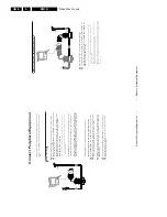
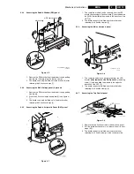
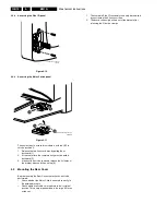
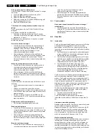
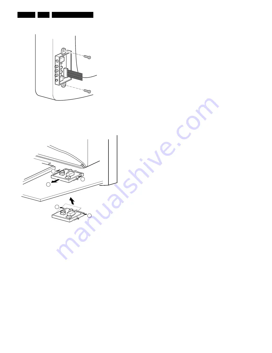
Accessing the Side I/O panel
Figure 4-10
1.
The complete Side I/O-assembly can easily be removed
by unscrewing the 2 fixation screws.
2.
The board can easily be lifted out of the bracket after
releasing the 2 fixation clamps.
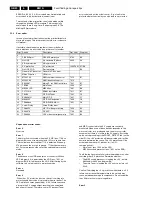
4.2.9
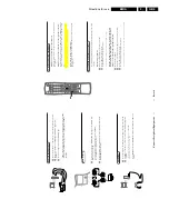
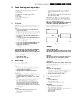
Accessing the Mains Switch panel
Figure 4-11
The easiest way to access this module is with the LSP in
service position 2.
1.
Release the two fixation clamps by pulling them
backward [1].
2.
At the same time, the complete assy must be pulled
backward [2].
3.
If the board has to be removed, release the 2 clamps at
the bracket sides and lift panel up [3].
4.3
Mounting the Rear Cover
Before mounting the Rear Cover, some checks has to be
performed:
•
Check whether the Mains Cord is mounted correctly in
the guiding brackets.
•
Check whether all cables are replaced in their original
position. This is very important due to the large 'hot' area
of the set.
CL 06532012_004.eps
030200
2
3
1
1
3
CL 06532130_018.eps
021000


