Fault finding and repair tips
GB 19
EM1A
5.
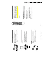
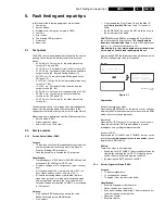
A question could be: Does the screen give a picture? (Click
on the correct answer)
YES / NO
An example can be: Measure test-point I7 and click on the
correct oscillogram you see on the oscilloscope
Figure 5-4
By a combination of automatic diagnostics and an interactive
question/answer procedure, ComPair will enable you to find
most problems in a fast and effective way.
Additional features
Beside fault finding, ComPair provides some additional
features like:
•
Uploading/downloading of pre-sets.
•
Managing of pre-set lists.
•
Emulation of the Dealer Service Tool.
5.4.2
SearchMan (Electronic Service Manual)
If both ComPair and SearchMan are installed, all the
schematics and the PWBs of the faulty set are available
when clicking on the hyper-link of a schematic or a PWB in
ComPair. Example: Measure the DC-voltage on capacitor
C2568 (Schematic/Panel) at the Monocarrier.
Clicking on the PWB hyper-link automatically shows the
PWB with a highlighted capacitor C2568. Clicking on the
schematic hyper-link automatically shows the position of a
highlighted capacitor at the schematic.
5.4.3
Connecting the ComPair interface
The ComPair Browser software should be installed and set-
up before connecting the ComPair interface to the TV-set
(see the ComPair Browser Quick Reference Card for
installation instructions).
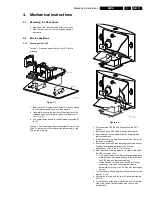
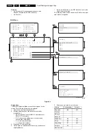
1.
Connect the RS232 interface cable to a free serial (COM)
port on the PC and the ComPair interface PC connector
(connector marked with 'PC').
2.
Connect the mains adapter to the connector marked
'POWER 9V DC' on the ComPair interface.
3.
Switch the ComPair interface 'OFF'.
4.
Switch the television set 'OFF' with the mains switch.
5.
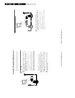
Connect the interface cable to the connector on the rear
side of the ComPair interface that is marked 'I
2
C' (see
figure 5-6).
6.
Connect the other end of the interface cable to the
ComPair connector on the monocarrier (left to the rear
cinch connectors).
7.
Plug the mains adapter in the mains outlet and switch
'ON' the interface. The green and red LEDs light up
together. The red LED extinguishes after approx. 1
second (the green LED remains lit).
8.
Start-up ComPair and select 'File' menu, 'Open...:; select
'EM1A Fault finding' and click 'OK'.
9.
Click on the icon to switch 'ON' the communication mode
(the red LED on the ComPair interface will light up).
10. Switch 'ON' the TV-set with the mains switch.
11. When the set is in standby, click on 'Start-up in ComPair
mode from standby' in the ComPair EM1A faultfinding
tree, otherwise continue.
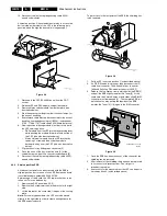
Figure 5-5
The set has now started up in ComPair mode. Follow the
instruction in the EM1A faultfinding tree to diagnose the set.
Note that the OSD works but that the actual user control is
disabled
5.4.4
Pre-set installation
Pre-sets can be installed via the service cable:
•
sending TO the television and reading FROM the
television
•
the rear cover does NOT have to be removed
Click on 'File', 'Open' and select 'EM1A fault finding' to use
the cable.
Pre-sets can be installed via menu 'Tools', 'Installation' and
'Pre-sets'.
5.4.5
Ordering ComPair
ComPair order codes:
•
Starter kit C SearchMan so ComPair
interface (excluding transformer): 4822 727 21629
•
ComPair interface (excluding transformer): 4822 727
21631
•
Starter kit ComPair software: 4822 727 21634
•
Starter kit SearchMan software: 4822 727 21635
•
Starter kit C SearchMan software: 4822 727
21636
•
ComPair CD (update): 4822 727 21637
•
SearchMan CD (update): 4822 727 21638
•
ComPair interface cable (for EM1A): 4822 727 21641
5.5
Error codes
5.5.1
Error buffer
The error code buffer contains all errors detected since the
last time the buffer was erased. The buffer is written from left
to right. When an error occurs that is not yet in the error code
buffer, the error is written at the left side and all other errors
shift one position to the right.
The error code buffer will be cleared in the following cases:
•
By activating 'CLEAR ERRORS' in the SAM menu:
–
Exiting SDM or SAM with the 'Standby' command on
the remote control (by leaving SDM or SAM with the
mains switch, the error buffer is not reset).
–
Transmitting the commands 'DIAGNOSE 99 OK' with
the DST (RC7150) or with ComPair
•
Automatically reset if the content of the error buffer has
not changed for 50 hours
Examples:
ERROR: 0 0 0 0 0 0 0 : No errors detected
ERROR: 6 0 0 0 0 0 0 : Error code 6 is the last and only
detected error
I7 B7502
1V / div DC
10
µ
s / div
CL96532160_029.eps
110100
PC
VCR
I2C
Power
9V DC
R
L
AUDIO
EXTERNAL 1
EXTERNAL 2
SERVICE
CONNECTOR

