Circuit descriptions and abbreviation list
GB 82
EM1A
9.
9.
Circuit descriptions and abbreviation list
9.1
Circuit descriptions
The following circuits are described:
1.
Introduction
2.
Block diagrams
3.
Power supply
4.
Control & Teletext
5.
Tuner & IF
6.
Video: High-end Input Processor
7.
Video: Feature box
8.
Video: High-end Output Processor
9.
Synchronisation
10. Horizontal deflection
11. Vertical deflection
12. Audio
13. CRT & SCAVEM
14. Double Window (DW)
9.1.1
Introduction
The EM1A is a lower specified MG-chassis. EM stands for
Eco-MG, 1 for the used processor (Painter) and A stands for
Asian Pacific.
The user interface and processor are the same as used in the
A10A set. In the EM1A however, a HIP, PICNIC and HOP are
used for the 100 Hz function i.s.o. the BOCMA in the A10A.
So the HIP and HOP have the same functionality as the
BOCMA (to let the set work in 2fH-mode), while the PICNIC
is used for video features like AutoTV and Freeze.
The architecture consists of a conventional Large Signal
Panel (LSP) a Double Window panel (DW) and a Small
Signal Board (SSB) module, placed into a so-called SIMM-
connector (Standard Interface, 80 pins).
The LSP is built up very conventional, with hardly any surface
mounted components on the copper side. Difference with the
MG-chassis is that the EM1A LSP has a very large 'hot' part,
including the deflection coil.
The SSB is a high tech module (2 sides reflow technology,
full SMC) with very high component density and complete
shielding for EMC-reasons. Despite this, it is designed in
such a way, that repair on component level will be possible.
To achieve this, attention has been paid to:
•
The position of service test lands (Tuner side).
•
Accessibility (Tuner side).
•
Clearance around surface mounted IC's (for replacing).
•
Diagnostics & Fault Finding via ComPair.
Warning: Be aware that half of the LSP-circuitry is 'hot',
including the deflection coil.
Protection: The start-up behaviour of the EM1A is different
then that of the MG-chassis, meaning that there does not
exist a situation as in the MG where we have 'supply ON/
deflection circuit OFF'.
This means that isolating failures in the EM1A must be done
in a different way. See Chapter 5 of this manual.
9.1.2
Block diagrams
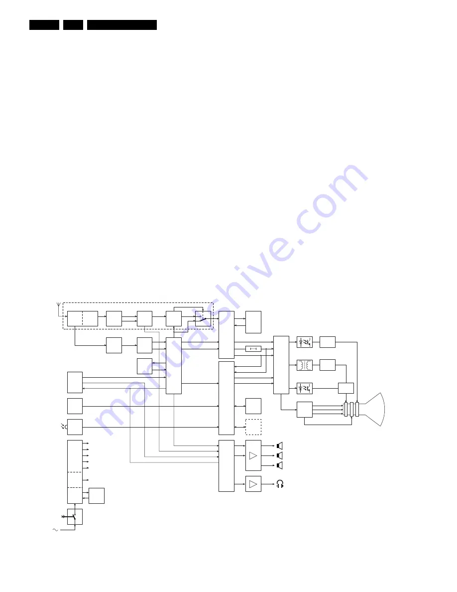
Figure 9-1
CL 06532130_019.eps
131000
HOR
SCAVEM
R
G
B
IF
FILTER
BOCMA
DW
PROC.
CRT
+
SCAVEM
SPLITTER
TUNER
PIP/DW
EXT
I/O
PIP/DW MODULE
VIF
SIF
YUV
FBL
YUV50
AUDIO-PIP
MSP
VIF
SIF
HA
VA
YUV
VD
VD100
VDHOP
HD100
FBL-TEXT
RGB-TEXT
AUDIO-EXT
MONITOR-OUT (A+V)
VIDEO-EXT
IR
REC.
POWER
SUPPLY
141V
EHT
180V
28V
ETC.
5V2
SIF
AUDIO-PIP
AUDIO-EXT
(A) MONITOR-OUT
L
R
HP
S/W
HP
R
L
CVBS-TEXT
TUNER
TOP
CONTROL
IF
FILTER
NVM
AMPL
TXT
RAM
COMB
FILTER
HIP
HOP
CRT
PICNIC (FBX)
PAINTER
PROZONIC
HD
E/W
E/W
VERT
LOW
POWER
STBY
MAINS
POWER
ON/OFF
MULTI
VOLTAGE
(V)

