Directions for use
GB 8
EM1A
3.
16
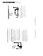
Connect P
eripheral Equipment
75
CABLE
VCR
AV 2
in
AV 1
in
Monitor
out
COMPONENT VIDEO INPUT
VIDEO
L/M
o
n
o
R
Y
Pb
Pr
AUDIO
S-VIDEO
OUT
OUT
OUT
IN
j
x
4
1
3
Video r
ecor
der and other
A/V
peripherals
&
Inter
connect y
our video r
ecor
der with extra RF cables
3
.
é
To
obtain better pictur
e quality
,also connect the
Video
,Audio left and
Audio
right (onl
y f
or ster
eo equipment) cables to the
VIDEO
,
A
UDIO L/
Mono
and
A
UDIO R
input of
A
V2 IN
sock
ets
4
.
Note:
in case of mono equipment,
only the left loudspeak
er reproduces sound.
Use a mono to stereo adaptor (not supplied) f
or sound reproduction via all
inter
nal loudspeak
er
s.
When a video recorder is not connected to
MONIT
O
R
O
UT
you can only record a
progr
amme from the aer
ial or from the cab
le system.
Only when a video recorder is connected to
MONIT
O
R
OUT
it is possib
le to record a
progr
amme from other equipment connected to the
TV
.See Record with your video
recorder
,p
.18.
15
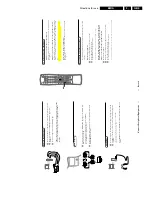
Connect P
eripheral Equipment
Connect P
eripheral Equipment
Ther
e is a wide range of audio and video equipment that can be connected
to y
our
TV
.The f
ollo
wing connection diagrams sho
w y
ou ho
w to connect
them.
&
Connect the RF cable
1
to the RF sock
et
x
of y
our video r
ecor
der
.
é
Connect another RF
cable
2
fr
om the output
j
of y
our video r
ecor
der to
the input
x
of y
our
TV
.
Better pla
yback quality can be obtained if y
ou also connect the
Video
,Audio
Left and Right (onl
y f
or ster
eo equipment) cables
3
to the
VIDEO
,
A
UDIO L/
Mono
and
R
input
A
V2 IN
.
Note:
in case of mono equipment,
only the left loudspeak
er reproduces sound.
Use a mono to stereo adaptor (not supplied) f
or sound reproduction via all
inter
nal loudspeak
er
s.
The
MONIT
OR OUT
connectors can be used f
or daisy chaining or to r
ecor
d
pr
ogrammes fr
om y
our
TV
.
See Recor
d with y
our video r
ecor
der
,p
.18.
S-VHS-Video
quality with a S-VHS video r
ecor
der is obtained b
y connecting
the
S-VHS-Video
cable with the
S-VIDEO
input instead of connecting the video
recor
der to the
VIDEO
input.
(See the instructions of y
our video r
ecor
der
.)
If the cables
3
ar
e not used the f
ollo
wing steps ar
e r
equir
ed:
Sear
ch f
or and stor
e the test signal of the video r
ecor
der
&
Unplug the RF cable
1
fr
om the RF sock
et
x
of y
our video r
ecor
der
.
é
Switch on y
our
TV and put the video r
ecor
der on the test signal or pla
y a
pr
er
ecor
ded ta
pe (See the handbook f
or y
our video r
ecor
der
.).
“
Sear
ch f
or the test signal of y
our video r
ecor
der in the same wa
y as y
o
u
sear
ched f
or and stor
ed the
TV signals.
See Installation,
Stor
e
TV Channels,
Man
ual T
uning,
p
.5.
‘
Stor
e the test signal under pr
ogramme n
umber 0 or betw
een 90 and 99.
(
Replace the RF cable in the RF sock
et
x
of y
our video r
ecor
der after
you ha
ve
stor
ed the test signal.
Video r
e
cor
der
CABLE
VCR
75
OUT
j
x
AV 2
in
AV 1
in
Monitor
out
COMPONENT VIDEO INPUT
VIDEO
L
/Mono
R
Y
Pb
Pr
AUDIO
S-VIDEO
3


