Circuit Descriptions and Abbreviation List
9.
In the PICNIC there are three nine bit ADCs present for Y, U,
and V. For digitizing the Y (luminance), nine bits are used (to
realize a more detailed picture.) These nine bits are only
internally used. Via dithering, the nine bits are reduced to eight
bits and this data is stored into memory. The data in the
memory is fed back to the PICNIC and via un-dithering the data
is again reproduced to nine bits for processing.
U/V (color difference signals) is also sampled with nine bits.
These two nine bit data streams are multiplexed to four bit data
streams. As the perception of colors by the human eye is less
sensitive to luminance, this reduction is allowed.
Interlaced to progressive scan conversion
The main function of the PICNIC is the 'Anolog-to-Digital'
conversion, spacial noise reduction, histogram functions (like
Dynamic Contrast and Black Stretch) for YUV and HV-sync
processing.
Also the line frequency (16 kHz) is doubled (32 kHz.)
De-interlacing itself is realized in the FALCONIC (Field And
Line CONverter IC).
Further features of the PICNIC/FALCONIC:
•
Dual Screen Compression. The PICNIC can provide
horizontal video compression up to 50 %. The compress
mode can be used to display dual screens.
•
The Panorama Mode. To fit 4:3 pictures into a 16:9
display, it is possible to apply a panoramic horizontal
distortion, to make a screen-fitting picture without black
sidebars or lost video. The center horizontal gain is
programmable and the side gain is automatically adapted
to make a screen-fit.
•
Automatic Aspect Ratio Adaptation (AARA.) This
feature uses data from the 'black bar detection circuit' to
adapt the vertical and horizontal amplitude to an aspect
ratio belonging to the display, without the black bars.
•
Dynamic Contrast. To make the contrast (black/white)
range wider, Philips has invented Dynamic Contrast. It
uses the digital memory used in 100 Hz sets. It measures
every A-field (25 x per second), and digitally analyses
where on the grayscale most of the image is located. If it is
a relatively dark image, the lighter part of that image is
stretched towards white, so that more contrast will become
visible in that picture. If it is a relatively light image, the
darker part of that image is stretched towards black, so that
these darker parts will have more contrast. When the
image is in the middle of the grayscale, both dark and light
parts are stretched.
9.8.4
Eagle (Diagram B3C)
Introduction
Some strong picture improvements are carried out inside the
Eagle, which all contribute to the excellent picture quality.
These improvements are:
•
LTI (both horizontal and vertical.)
•
CTI (only horizontal.)
•
Peaking (both horizontal and vertical.)
•
More pixels per line.
•
More lines per frame.
•
Better color representation for skin tones, green, and sky.
By means of over sampling, the video signals get a sample
frequency of 64 MHz, a bandwidth of 20 MHz, and 1680 pixels
per line (previously 32 MHz, 10 MHz and 840 pixels/line.) This
requires two extra field memories (MEM4 and MEM5.)
The Eagle can handle four different modes:
•
Digital Natural Motion (PAL): 100 Hz, 2f
H
, 2:1 Interlace
(2048 pixels x 625 lines)
•
Pixel Plus (PAL): 75 Hz, 2f
H
, 2:1 Interlace (2048 pixels x
833 lines)
•
Double Lines (PAL): 50 Hz, 2f
H
, 2:1 Interlace (2048 pixels
x 1250 lines)
•
Pixel Plus (NTSC): 60 Hz, 2f
H
, 2:1 Interlace (2048 pixels x
1050 lines)
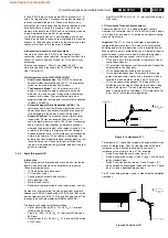
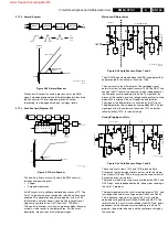
LTI (Luminance Transient Improvement)
The main objective of LTI is a steeper slope at contrast
transitions (for example, from 10 mV to 900 mV within 3 pixels
i.s.o. 5 pixels for one detail.) It is based on waveform altering
around a signal jump.
Important: The LTI, as used in the Eagle, is designed for
interpolated picture contents. This means that for pixel/line
doubling, one of the two pixels/lines is an interpolated value.
When a picture jump is interpolated, you will get extra room to
make it steeper (you get extra pixels to describe the slope.)
Without interpolation, you cannot use this kind of LTI.
•
LTI can add 'ears' to the waveform at the jump (a kind of
controlled overshoot.)
•
LTI 'estimates' the frequency of the jump and will adapt the
amplification to this frequency.
•
LTI is applied both horizontally and vertically.
•
LTI is amplitude dependent. This means that only 'big'
jumps are processed. It works with a threshold, which is
coupled to the noise meter via the Auto TV software.
•
LTI is also frequency dependent. This means that it is
distributed over the slopes. When there are many steep
slopes in the signal, LTI will only process the steepest
ones. If there are only a few slopes, LTI will process all of
them. This is fully hardware implemented.
Figure 9-13 Horizontal LTI
For horizontal LTI, the number of pixels is doubled (64 MHz) by
means of interpolation. Pixel A at the transition will keep its
luminance value, while the (new) pixels B can have a
luminance value of zero to max. 31. For example:
•
Pixels B can keep the same value (gain = 0)
•
Pixels B can get the value of C and C' (gain = 8), which will
give a steeper slope.
•
Pixels B can also get the value of D and D' (gain = 31),
which will give an even steeper slope with the 'ears.' These
'ears' will give a contrast improvement.
For CTI, the same principle is used, in order to get better color
transitions.
Figure 9-14 Vertical LTI
Luminance Y
spatial X or Y
Original slope
Added interpolated
pixels
B
B
A
C'
D'
C
D
CL 16532149_083.eps
061201
gain=0
gain=8
gain=31
CL 26532058_023.eps
110602
detail
Original samples
Added interpolated
samples
1050
samples
www.freeservicemanuals.info
Summary of Contents for EM5A NTSC
Page 6: ...Direction for Use EN 6 EM5A NTSC 3 3 Direction for Use www freeservicemanuals info ...
Page 7: ...Direction for Use EN 7 EM5A NTSC 3 www freeservicemanuals info ...
Page 8: ...Direction for Use EN 8 EM5A NTSC 3 www freeservicemanuals info ...
Page 9: ...Direction for Use EN 9 EM5A NTSC 3 www freeservicemanuals info ...
Page 10: ...Direction for Use EN 10 EM5A NTSC 3 www freeservicemanuals info ...
Page 11: ...Direction for Use EN 11 EM5A NTSC 3 www freeservicemanuals info ...
Page 12: ...Direction for Use EN 12 EM5A NTSC 3 www freeservicemanuals info ...
Page 13: ...Direction for Use EN 13 EM5A NTSC 3 www freeservicemanuals info ...
Page 14: ...Direction for Use EN 14 EM5A NTSC 3 www freeservicemanuals info ...
Page 15: ...Direction for Use EN 15 EM5A NTSC 3 www freeservicemanuals info ...
Page 16: ...Direction for Use EN 16 EM5A NTSC 3 www freeservicemanuals info ...

