Circuit Descriptions and Abbreviation List
EN 128
9.
The principle for vertical LTI is the same as for horizontal LTI.
The shift from 525 to 1050 lines is done by means of a scaler.
With these extra-interpolated samples, it is possible to create
steeper slopes, possibly with 'ears.'
Peaking/Coring
The objective of 'peaking' is contrast improvement (for
example, from 50 mV
PP
to 70 mV
PP
for one detail.)
It uses a noise threshold (coring = non-linear filtering around
zero-level), thus it works everywhere in the picture (except
below the threshold level.)
The added difference signal is frequency dependent, which
results in frequency dependent contrast improvement. When
the difference signal becomes too large, the peaking is reduced
(smartness.)
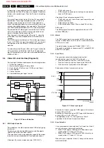
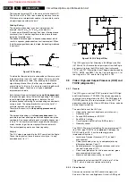
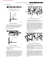
Figure 9-15 Peaking
To obtain the filter characteristic shown above, filters are set at
three parameters (see A, B, and C above.) This way, only the
higher frequencies are 'lifted.' After sending the luminance
signal through these filters, the filter output is added to the
original signal. In this way, the 'ears' are created, together with
the steeper slopes. These 'ears' will give a contrast
improvement at details.
Both horizontal and vertical peaking is amplitude dependent:
the higher the signal jump, the lower the peaking. This is done
to avoid high jumps getting big 'ears,' because this will
introduce uneven contouring. To avoid peaking on noise levels,
coring is used. The coring threshold is set via the Auto TV
software, by means of the noise meter.
Therefore, the result is that the peaking processes only
details.
The horizontal peaking is also frequency dependent: it is
possible to perform peaking around three frequencies (when
combined, it is even possible to peak at variable frequencies.)
In Auto TV, this feature is software coupled to the sharpness
meter, in order to get the most optimal filter characteristic.
The vertical peaking works on a fixed frequency.
Output
The YUV signals presented to the HOP come from the Eagle.
These three signals all have the same circuitry so it is only
explained once (for Y.)
Figure 9-16 YUV Output Filter
The YUV signals are first filtered by a 64 MHz passive filter
(L5739 with C's.) Because the output signals from the Eagle
are too small to drive the HOP directly, the circuit around
TS7731 and TS7728 amplifies them. The gain is determined by
R3791, R3788, and R3807. For the Y-signal the gain is 2, for
the U-signal it is 1.33, and for the V-signal it is 1.05.
9.9
Video: High-end Output Processor (HOP) and
TOPIC (diagram B4)
9.9.1
General
The YUV-signals from the PICNIC are fed to the HOP (High-
end Output Processor, TDA9330.) The video and geometry
control parts are integrated in the HOP. The RGB-signals for
CC/OSD (from the
µ
P) are also inserted via the HOP. The
geometry part delivers the H-drive, EW-drive, V-drive, and also
a drive signal for rotation.
The main functions of the HOP are:
•
Video control (contrast, brightness, saturation, etc..)
•
Deflection drive.
•
Second RGB interface for OSD/CC.
•
Peak White Limiting.
•
Cut-off control and White Drive (RGB outputs.)
•
Geometry control.
The TOPIC (The most Outstanding Picture improvement IC,
item 7302, type TDA9178) is an optional IC between the
PICNIC and the HOP. It has the following (picture
improvement) functions:
•
Luminance Transient Processor (LTP), for detail
enhancement.
•
Chrominance delay circuitry, to compensate timing
differences between Y and C.
•
Spectral processor, for improved sharpness and color
transient improvement (CTI.)
•
Color vector processor, for skin tone correction, green
enhancement and blue stretch.
•
Measure and detection circuitry, for AutoTV.
The sandcastle pulse from the HOP is fed to pin 1 of the
TOPIC, which is used as a reference for timing.
9.9.2
Video Control
After source selection, the HOP controls the signals for
Saturation, Contrast, and Brightness. Output is RGB again.
CL 16532149_085.eps
131201
Amplitude
Frequency
PEAKING
'ear'
'ear'
B
A
C
2.3Mc
4Mc
8Mc
CL 26532041_076.eps
170402
Y100
3700
2701
5700
2700
GND
2702
GND
3703
GND
GND
7728
+8V
7731
GND
5739
GND
GND
GND
GND
Y-EAGLE
(pin54)
www.freeservicemanuals.info
Summary of Contents for EM5A NTSC
Page 6: ...Direction for Use EN 6 EM5A NTSC 3 3 Direction for Use www freeservicemanuals info ...
Page 7: ...Direction for Use EN 7 EM5A NTSC 3 www freeservicemanuals info ...
Page 8: ...Direction for Use EN 8 EM5A NTSC 3 www freeservicemanuals info ...
Page 9: ...Direction for Use EN 9 EM5A NTSC 3 www freeservicemanuals info ...
Page 10: ...Direction for Use EN 10 EM5A NTSC 3 www freeservicemanuals info ...
Page 11: ...Direction for Use EN 11 EM5A NTSC 3 www freeservicemanuals info ...
Page 12: ...Direction for Use EN 12 EM5A NTSC 3 www freeservicemanuals info ...
Page 13: ...Direction for Use EN 13 EM5A NTSC 3 www freeservicemanuals info ...
Page 14: ...Direction for Use EN 14 EM5A NTSC 3 www freeservicemanuals info ...
Page 15: ...Direction for Use EN 15 EM5A NTSC 3 www freeservicemanuals info ...
Page 16: ...Direction for Use EN 16 EM5A NTSC 3 www freeservicemanuals info ...


