Circuit Descriptions and Abbreviation List
EN 134
9.
The supply voltage is a symmetrical voltage of +/- 16 V (or +/-
19 V, depending on the set execution), generated by the main
supply via L5512 (or L5506.)
Mute
Sound muting is performed by the STBY-MUTE line connected
to pin 6 (tri-state input) of the amplifier IC. This line is activated
via the SOUND-ENABLE line (software controlled) and/or POR
line (hardware controlled.)
This signal is inverted by TS7701 and/or TS7703, and as a
result, at a high level of the SOUND-ENABLE signal, current is
sinked from pin 2 and the IC mutes.
Protection
A loudspeaker DC protection is implemented. The amplifier IC
TDA7490 has a 'standby-mute-play' feature via the tri-state
input pin 6. When the voltage on pin 6 is:
•
0 - 0.7 V, the IC is in 'standby' mode
•
1.7 - 2.5 V, the IC is in 'mute' mode
•
4 - 5 V, the IC is in 'play' mode (normal operation.)
Note: This is a 'local' protection, not controlled by the
microprocessor.
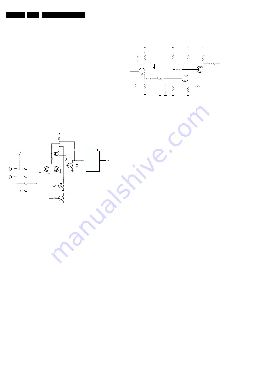
Figure 9-24 Loudspeaker DC-protection
This works in the following way:
•
During normal operation, V
X
is 'low' (0 V) and V
Y
is 'high'
(+5 V.)
•
When a positive DC-voltage is detected on a loudspeaker
output (= V
X
), TS7704, TS7706, and TS7707 will conduct,
making V
Y
'low.'
•
When a negative DC-voltage is detected on a loudspeaker
output (= V
X
), TS7705, TS7706, and TS7707 will conduct,
also making V
Y
'low.'
•
When V
Y
is 'low' (read 0 V), the tri-state input (pin 6) puts
the amplifier IC in 'standby' mode.
9.14.6 Headphone Amplifier (Diagram B10)
The headphone amplifier is a straightforward OpAmp amplifier
(IC7681, NJM4556.) It is supplied with +8 V.
9.15 Closed Caption (Diagram B5)
The CC-decoder in the OTC gets its video signal directly on pin
5 (from the HIP.)
The RGB-outputs are available on pins 77/78/79. Fast blanking
is realized via pin 80.
9.16 CRT Panel / Rotation
9.16.1 RGB Amplifiers (Diagram F1)
Figure 9-25 RGB signal path
The RGB signals from the HOP are fed to three identical
amplifiers (TDA6118) on the CRT panel. We will use one of
them (B, connector 1940 pin 9) as an example for this
description.
After emitter follower TS7506, the signal is fed to TS7507 and
TS7508. This circuit sends the signal, with the same DC-
voltage, to the RGB amplifier (IC7350, pin 3.) In order to cope
with the higher picture definition, this IC has a larger bandwidth
than the previous ones. The cathodes of the picture tube are
driven via outputs 8.
The supply voltage for the amplifiers is 200 V and is derived
from the LOT.
The delay line item 5502 compensates for group delay time
differences between Scavem and the RGB signals.
9.16.2 Rotation (Diagram A5)
In sets with a rotation coil (wide screen sets), the amount of
frame rotation is adjusted with the 'Tilt' DAC-output of the HOP
pin 25 (see also 'Vertical Deflection'.)
9.17 Auto Scavem (Diagrams SC1 and F2)
9.17.1 Introduction
To improve the sharpness, the Scan Velocity Modulation
(Scavem) circuit modulates the deflection speed as a function
of the picture contents. This feature uses a separate Scavem
deflection coil.
Auto Scavem is introduced, to be able to display the high
definition signal from the FBX7. Since the Auto TV software
now controls the Scavem circuit, it is called Auto Scavem.
The circuit with the Scavem amplifier, is located on a separate
CBA (parallel to the SSB), and is connected to the picture tube
panel.
CL 16532044_017.eps
140501
OUT
R
L
(RES)
C/SW
(PROT 1)
2778
7704
47K
47K
10K
+5V
47K
33K
7705
2705
7707
470N
VY
OUT
6
23
VX
7703
7706
7701
10K
10K
Sound Enable
POR
SOUND-IC's
7700/7702
STANDBY-MUTE
(TRISTATE)
100K
10K
CL 26532058_017.eps
050602
To TDA6118
(pin 3)
3529
100R
1K2
3525
9503
100n
GND_RGB
GND_RGB
GND_RGB
GND_RGB
7506
BC847B
1K5
3523
2505
100R
3537
GND_RGB
820R
3528
7508
BC857B
680R
3526
B
1K5
3524
100R
3530
7507
BC847B
SDL
5502
560R
3543
3542
100R
2506
1p
3527
470R
3522
470R
2303
1p
3521
560R
GND_RGB
+8V
+8V
+8V
+8V
www.freeservicemanuals.info
Summary of Contents for EM5A NTSC
Page 6: ...Direction for Use EN 6 EM5A NTSC 3 3 Direction for Use www freeservicemanuals info ...
Page 7: ...Direction for Use EN 7 EM5A NTSC 3 www freeservicemanuals info ...
Page 8: ...Direction for Use EN 8 EM5A NTSC 3 www freeservicemanuals info ...
Page 9: ...Direction for Use EN 9 EM5A NTSC 3 www freeservicemanuals info ...
Page 10: ...Direction for Use EN 10 EM5A NTSC 3 www freeservicemanuals info ...
Page 11: ...Direction for Use EN 11 EM5A NTSC 3 www freeservicemanuals info ...
Page 12: ...Direction for Use EN 12 EM5A NTSC 3 www freeservicemanuals info ...
Page 13: ...Direction for Use EN 13 EM5A NTSC 3 www freeservicemanuals info ...
Page 14: ...Direction for Use EN 14 EM5A NTSC 3 www freeservicemanuals info ...
Page 15: ...Direction for Use EN 15 EM5A NTSC 3 www freeservicemanuals info ...
Page 16: ...Direction for Use EN 16 EM5A NTSC 3 www freeservicemanuals info ...


