Circuit Descriptions and Abbreviation List
9.
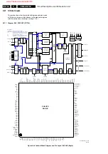
Figure 9-33 Double Window circuitry
9.18.2 IF and Video section
The IF and Video processing in the DW module is performed
by a BOCMA IC, in the set by the HIP IC. There is also a PIP
processor.
For NAFTA execution, two antenna inputs are possible. One
for off-air and one for cable, or both off-air or cable.
‘IF-TER’ from the tuner is fed to pin 1 and 2, IF circuits of
TDA8887H IC7301 via SAW filter 1352. The AGC voltage for
the tuner can be adjusted in the SAM tuner menu (2nd AGC.)
In order to display the external AV sources by the DW panel, a
source selection circuit is incorporated on the panel. Three
external AV sources are possible (AV1-YUV, AV2-SVHS2, AV-
FRONT.) IC7401 HEF4053 performs the selection between
these sources.
The YUV is fed directly to video processor IC7301. The IC
performs this source selection internally.
The video processor IC7301 decodes the CVBS at pin 24 or pin
29 into YC signal and further process it into YUV signal and
output at pin 40, 45, and 46. ‘PIP-AUDIO’ is fed to pin 47 of the
audio demodulator MSP34x2 on the SSB.
9.18.3 DW/PIP processing
IC7801 SAB9081 is a multi-standard PIP controller, which can
be used in double window or PIP applications. The YUV from
the video processor IC7301 is fed to pin 79, 81, and 83. IC7801
will insert YUV from the IC7301 with reduced size into the main
picture YUV source in a PIP environment. The main picture
YUV is fed to pins 100, 2, and 98, respectively. These signals
are mainly used during the DW mode.
Inside IC7801, the conversion to the digital environment is
done on a chip with ADCs. Processing and storage (1 MB
DRAM) of the video data is done entirely in the digital domain.
The conversion back to the analog domain is done by DACs.
Internal clocks are generated by PLLs, which lock on to the
applied horizontal and vertical syncs from the main and sub
pictures. The main picture syncs are applied to pin 70 (vert.)
and pin 94 (hor.) and the sub picture syncs are applied to pin
72 (vert.) and pin 87 (hor..)
For DW mode, the main picture is compressed horizontally by
a factor of two and fed directly to the output. After compression,
a horizontal expansion of two is possible for the main picture.
The sub picture is also compressed horizontally by a factor of
two but stored in memory before it is fed to the outputs.
Post-processed YUV signals are fed to fast switching IC7803
TDA8601 pins 6, 7, and 8. In normal operation (without DW),
the main picture YUV signals (at pins 2, 3 and 4) are bypassed
by IC7803, and returned back to the main video processor.
When DW mode is active, the compressed YUV signals (main
and sub pictures) are used and fed to the main video
processor. During the PIP mode, only sub-picture YUV signals
are used. The insertion control is made possible by a fast
blanking signal from pin 68 of IC7801.
9.18.4 V-Chip
For the movie rating blocking requirements, a data-slicer is built
on the DW panel. IC7501 Z86130 will decode the V-Chip
coding for the DW picture. The source for decoding is made
possible by the ‘SEL_PIP_CVBS’ signal at the IO port of
IC7301 pin 60. When this signal is ‘low,' Tuner 1, Tuner 2, or
AV CVBS is selected. When this signal is ‘high,' the external
YUV is selected.
9.18.5 Power supplies
The power supplies used by the DW panel are from the main
board 5 V, 8 V, and 33 V (for tuner only.) IC7802 LM317T
regulates the 5V to +3.3V, +3V, and +3VD. These voltages are
mainly used by the DW processor circuitry. The 8V is mainly
supplied to IC7301 TDA8887H IF + video processing circuitry,
and to fast switching IC7803.
9.19 Software Related Features
The following features are described:
•
Auto TV
•
'Switch On' Behavior
9.19.1 AutoTV
The AutoTV (or 'Automatic Picture Control' or 'Active Control')
aims at giving the customer the best possible picture
performance at any time. It is a collection of algorithms that
control the image processing parameters, depending on the
picture properties retrieved from meters or information in the
main software.
The following sub-systems are defined for Auto-TV. They are
present or absent according to the hardware configuration of
the set.
•
Auto Noise Reduction. This algorithm measures the
amount of noise in the incoming video signal (this is done
by the LIMERIC part of the PICNIC.) As a result of this
measurement, the amount of noise in the picture is
corrected, starting from the noise level which is unpleasant
to the customer. Which parameters can be used is
dependent on the hardware.
•
Auto Sharpness. This algorithm measures the amount of
sharpness via the bandwidth of the incoming video signal
and adapts the peaking frequency in the PICNIC according
to this info. If the 'sharpness meter' sees the video content
as 'sharp,' high frequency peaking will be used. On the
other hand, if the picture content is seen as 'not sharp,' a
low/mid frequency peaking is used.
•
Auto Ambient. The picture performance is adapted to the
ambient conditions (via the light sensor.)
TUNER - 7201
1352
4
5
1
11
IF
+
+
RGB/
YUV
INPUT2
RGB/YUV
MATRIX
COLOUR
DECODING
SYNC
RBG/YUV
MATRIX
YUV INTERFACE
RGB
INPUT1
RGB
OUTPUT
DOUBLE WINDOW PROCESSOR
IC7801
SAB9081H
TDA8887H
IC7301
(=BOCMA)
7803
TDA8601
1333
4
3
0
5
PIP-AUDIO
P
IP
-A
U
D
IO
12
11
10
6
7
8
8
12
10
10
6 8 9
2
3
4
4 3 1
0205
Y
-M
A
IN
-O
U
T
U
-M
A
IN
-O
U
T
V
-M
A
IN
-O
U
T
Y
-P
IP
+
M
A
IN
-IN
U
-P
IP
+
M
A
IN
-IN
V
-P
IP
+
M
A
IN
-IN
98
2 100
40 45 46
83
79
81
56
49
87
72
S
V
S
Y
N
C
S
H
S
Y
N
C
D
V
S
Y
N
C
D
H
S
Y
N
C
94
70
1
2
8
16
CVBS-PIP_TUN1-2-CVBS-IN
AP & LATAM
24
29
20
CVBS-SC1_AV1-IN
SEL_TUNER1
SEL_TUNER2
7402-B
7402-A
CVBS_TER_OUT
(to HIP on LSP)
Y-CVBS-FRONT-IN
Y-CVBS-SC2-AV2-IN
C-SC2_SVHS-IN
C-FRONT-IN
SEL-MAIN-R1R2
SEL-FRNT-RR
2
1
15
10
12
13
11
14
7401-C
7401-B
7401-A
12
13
14
11
5
3
4
2
1
15
10
9
41
42
43
R
-S
C
1
-IN
_
V
-IN
G
-S
C
1
-IN
_
Y
-IN
B
-S
C
1
-IN
_
U
-IN
7402-C
4
5
3
7501
V-CHIP
SDA
(AVI)
SCL
14
15
7
SEL_PIP_CVBS
54
7403
IO
EXPANDER
4
5
6
7
9
10
11
12
3
2
SEL-MAIN-R1R2
SEL-FRNT-RR
SEL_TUNER1
SEL_TUNER2
FBLK
N.A.
N.A.
N.A.
26
60
SDA
SCL
68
M
Y
M
U
M
V
S
V
S
U
S
Y
DV
DY
DU
CL 16532043_017.eps
190601
www.freeservicemanuals.info
Summary of Contents for EM5A NTSC
Page 6: ...Direction for Use EN 6 EM5A NTSC 3 3 Direction for Use www freeservicemanuals info ...
Page 7: ...Direction for Use EN 7 EM5A NTSC 3 www freeservicemanuals info ...
Page 8: ...Direction for Use EN 8 EM5A NTSC 3 www freeservicemanuals info ...
Page 9: ...Direction for Use EN 9 EM5A NTSC 3 www freeservicemanuals info ...
Page 10: ...Direction for Use EN 10 EM5A NTSC 3 www freeservicemanuals info ...
Page 11: ...Direction for Use EN 11 EM5A NTSC 3 www freeservicemanuals info ...
Page 12: ...Direction for Use EN 12 EM5A NTSC 3 www freeservicemanuals info ...
Page 13: ...Direction for Use EN 13 EM5A NTSC 3 www freeservicemanuals info ...
Page 14: ...Direction for Use EN 14 EM5A NTSC 3 www freeservicemanuals info ...
Page 15: ...Direction for Use EN 15 EM5A NTSC 3 www freeservicemanuals info ...
Page 16: ...Direction for Use EN 16 EM5A NTSC 3 www freeservicemanuals info ...

