Circuit Descriptions, Abbreviation List, and IC Data Sheets
9.
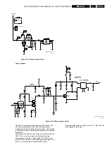
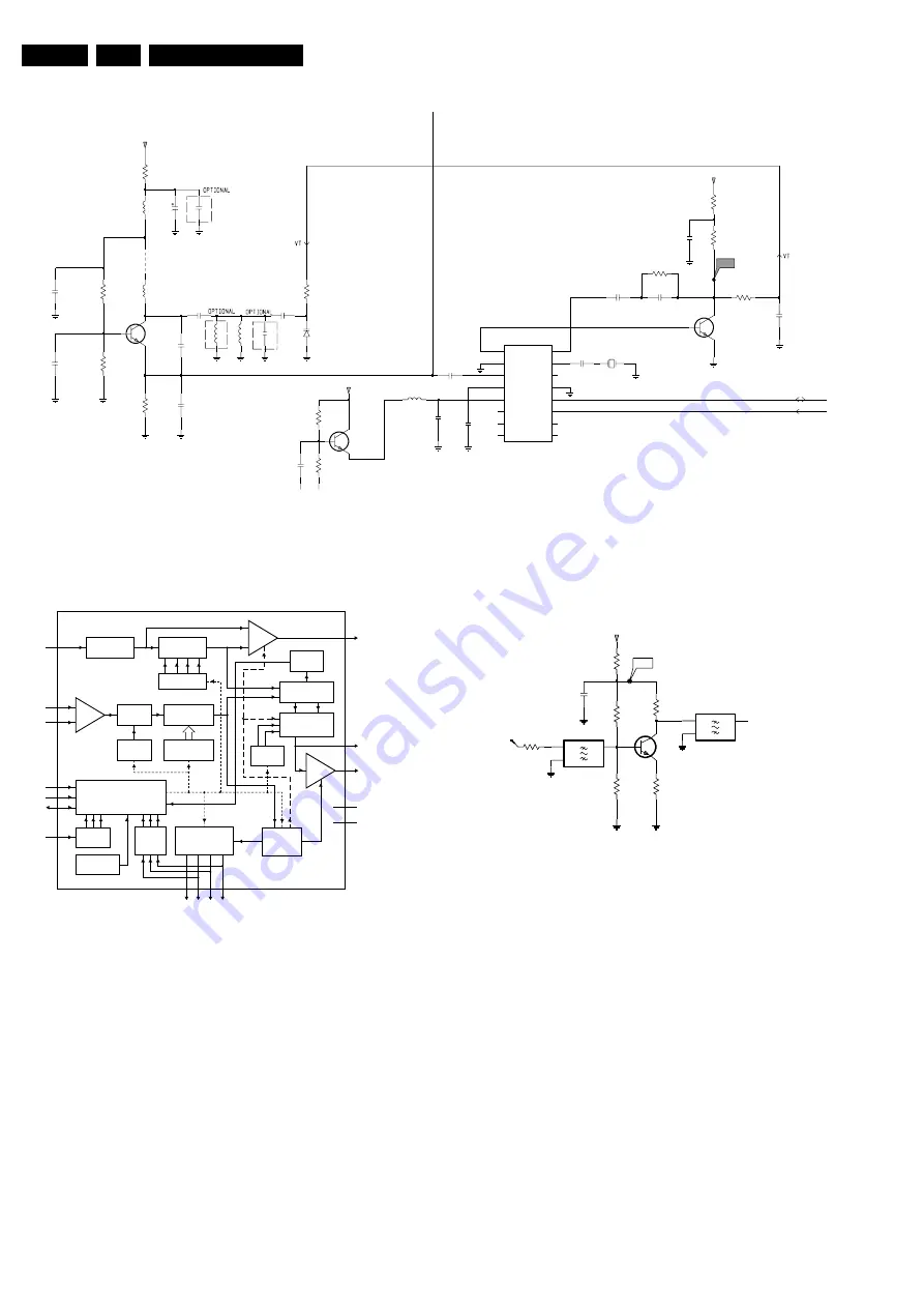
Synthesizer and Local Oscillator
Figure 9-23 Synthesizer circuit
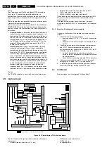
The internal circuitry of the TSA5060A can be seen in figure
below.
Figure 9-24 Block diagram TSA5060A
The TSA5060A is software controlled via the I2C bus by the
PIC12C508 microcontroller.
There is no hardware version recognition foreseen but the
version can be read out from the PIC12C508 microcontroller.
There is a different software code for the 433, 864, or 914 MHz
version.
The reference quartz crystal is 4 MHz and is divided to a lower
reference frequency of 200 kHz or 100 kHz (depending on the
version). The PLL filter is passive and includes 2625, 2626,
3615, 3611, and 2612. The transistor 7604 is part of the PLL
current source, and allows connection to higher supply
voltages as +5V.
The local oscillator (LO) is a common base transistor (7603)
that is oscillating at the fundamental frequency. The frequency
is tuned by the varicap 6601 until the tuning voltage is in the
range of the loop filter (between 0.5 and 7 Vdc). If the voltage
is outside this range then possibly, the division ratio is chosen
outside the normal range or some frequency dependant
component around the transistor is faulty.
IF Amplifier
Figure 9-25 IF amplifier circuit
The mixer output signal is filtered by two ceramic IF filters. An
IF amplifier (7707) is reducing the loss introduced by these
filters.
5n0
5607
2p7
2616
F749
15K
3608
7603
BFR92A
5608
2K2
3618
4K7
3616
7606
BC847B
F749
2p7
2619
5K6
3606
6601
BB151
4p7
2613
3607
220n
2626
2642
220n
5601
1p8
2622
BC847B
7604
13
RFA
14
RFB
6
SCL
5
SDA
12
VCC
2
XTAL
3
XT|COMP
220n
2612
TSA5060ATS
7605
11
ADC
4
AS
1
CP
16
DRIVE
15
GND
10
P0
9
P1
8
P2
7
P3
6K8
3609
16V
10u
2650
100R
3630
5616
3n9
AT-51
1609
4M
220R
3611
2p7
2620
560R
3615
1p0
2623
33p
2655
2615
33p
5617
2u2
2625
18p
2624
1n0
2606
2661
220n
3632
1K0
3631
390R
33p
2618
220R
3610
220n
2627
+8V
CL
DA
+8V
+8V
SYNTHESIZER
OSCILLATOR
CL36532008_079.eps
130503
CL36532008_071.eps
010503
FCE717
PRE
AMP
AMP
LOCK
DETECT
DIGITAL PHASE
COMPARATOR
CHARGE PUMP
REFERENCE
DIVIDER
DIVIDER
1/2
17-BIT
DIVIDER
17-BIT LATCH
DIVIDE RATIO
I
2
C-BUS
TRANSCEIVER
1-BIT
LATCH
2-BIT
LATCH
3-BIT
ADC
POWER-ON
RESET
MODE
CONTROL
LOGIC
3-BIT
INPUT
PORTS
4-BIT LATCH
AND
OUTPUT PORTS
XTAL
OSCILLATOR
4-BIT LATCH
2
XTAL
13
RFA
14
RFB
4
AS
6
SCL
5
SDA
11
10
9
8
7
ADC
CP
1
XT/COMP
3
DRIVE
16
VCC
12
GND
15
TSA5060A
P3 P2 P1 P0
O
GND
I
O
GND
I
SFELA
10M7
7707
BFS20
1707
3710
470R
3707
330R
2706
22n
3708
47R
F709
10M7
SFELA
1706
100R
3705
F709
3709
180R
3706
3K9
IF
+8V
IF AMP
CL36532008_082.eps
290403

