Circuit Descriptions, Abbreviation List, and IC Data Sheets
9.
Tuning
The tuning-concept of Self Tuned Radio (STR) is based on
"fuzzy logic": it mimics hand tuning (hand tuning is a
combination of coarse and fine-tuning to the qualitatively best
frequency position). Consequently, the tuning system is very
fast.
The tuning algorithm is completely integrated; so there are only
a few external components needed.
The bus only consists of three wires (BUS-CLOCK, DATA and
WRITE-ENABLE), so the bus and the microcontroller can be
kept very simple. The microcontroller must basically give two
instructions:
•
Preset operation. In this mode, the microcontroller has to
load information such as frequency band, frequency, and
mono/stereo. This information has to be sent via the bus to
the STR. After the AFC has tuned the real frequency to the
desired frequency, an in-lock signal can be generated. In
the FM mode the tuning voltage controls the VCO of the
external FM front-end and the frequency of the VCO is
counted in the TEA5762.
•
Search operation. During a search operation, the only
action the microcontroller has to take is: sending the
desired band plus the direction and the search sensitivity
level to the STR. STR. The search operation is performed
until an in-lock signal is generated. The AFC then fine
tunes to the station. The frequency belonging to the found
station will be counted by the counter and written into the
last-station memory and the shift register of the counter. At
this time, the frequency is available in the shift register and
can be read by the microcontroller. The microcontroller
decides whether the frequency is within the desired
frequency band. If so, this frequency can be stored under
a preset and if not, a new search action should be started.
The Bus
The TEA5762 radio has a bus, which consists of three wires:
•
BUS-CLOCK, software driven clock input (pin 27).
•
DATA, data input / output (pin 28).
•
WRITE-ENABLE, write / read input (pin 29).
These three signals, together with the mono/stereo pin (MO/
ST; pin 24), communicate with the microcontroller on the
interface board.
The mono/stereo indicator has two functions, which are
controlled by the BUS-CLOCK: "mono/stereo" and "tuned/not
tuned".
9.8.3
Basic fault finding on the tuner module.
If there is a malfunction of the module, one can proceed as
follows:
1.
Check the available supply voltages
–
Incoming supply 12 V (10 - 14 V on pin 4 of connector
1120)
–
Supply of IC7101: pin 7 must be 7.8 V, and pin 22 must
be 11 V.
2.
Check the data communication between microprocessor
and IC7101. Select other preset and check with an
oscilloscope if data is send on pin 29 (WRITE_EN), pin 27
(CLOCK), and pin 28 (DATA).
–
If no data transfer can be seen when activating a
button on the RC, the problem must be located around
the microprocessor.
–
If data transfer is occurring, probably 7101 is defective.
3.
If data communication towards 7101 is OK, the switch
settings (pins 30 and 31) of 7101 can be checked.
4.
At this point the standard fault locating can be started, as
usual from AF output working towards RF input.
9.9
LCD Board
See description in next paragraph "Interface Board".
9.10
Interface Board
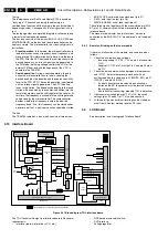
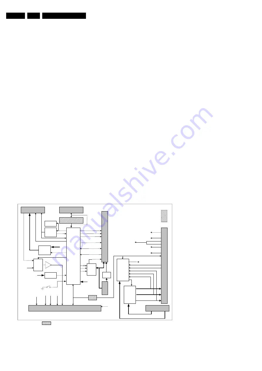
Figure 9-31 Block diagram TDL interface board
The TDL (Technical Design Line) interface board fulfils several
requirements:
•
Interface (radio, motor driver, LCD, etc.).
•
RDS decoder and audio switch.
•
DVD interface.
•
Voltage regulator.
P89C664
µC
LCD
assy
SAA6588
RDS Dec
RADIO_LEFT, RADIO_RIGHT
RADIO_ENABLE
+12V_ENABLE
I2C-SW
Power
Switch
+12V_STBY
DVD_LEFT
DVD_RIGHT
AUDIO
Switch
AMP
LM833
DAVN
Motor
Drive
L9997
CVBS
R,G,B
µSW1, µSW2
EN
IN1
IN2
LCD_ENABLE
LCD_DATA(0-7)
EEPROM
24C32
Reset
PCF1252
+5V_SW
RX,TX
RS232 driver only for
development
RADIO_DATA, RADIO_CLOCK,
RADIO
_
STEREO
SPDIF
PCF8574
IO
Expander
DVD
SUPPLY
I2C-S
+12V_DVD_OK
IRQ
DVD_IRQ
DVD_STDBY
+5V_DVD_OK
+3V3_DVD_OK
DVD_EJECT
MOT+,MOT-
LCD_BACKLIGHT
RS232
Eco-6 radio module
+12V_AUDIO
30P
DVD
DVD
Ejec
Supply from LSP
+5_2V_MP
+11V
I2C-S
I2C
I2C-S
DVD_LEFT
DVD_RIGHT
FFC TO SSB_TOP (30P or 14P)
Y
/CVBS
R*,G*,B*
SPDIF*
LCD_RS
LCD_RW
1253
1260
1280
1120
1250/1252
1146
1239
IRQ
MUTE
C*
+12V_DVD_OK
+5V_DVD_OK
+3V3_DVD_OK
Y
C
Y/CVBS
Supply fro
m
SSB_TOP
+12V_STBY
1U02
+5V
Flash Prog
Mode
AUDIO_LEFT
AUDIO_RIGHT
Not stuffed for Technical Design Line application
+5V_SW
5V Rise
time
control
+5V_SW
CL 36532049_001.eps
100603


