Circuit Descriptions, Abbreviation List, and IC Data Sheets
9.
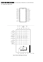
This panel has 2 diversities:
•
Full spec: all components stuffed.
•
Eco TDL: has no DVD, so the PCF8574, supply of DVD,
and connectors 1146 and 1253 are not stuffed.
9.10.1
Interface Control
The 89C66x is a new family of microcontrollers derived from
the 87C65x but with on-chip flash memory i.s.o. an EPROM.
This (slave) microcontroller has hardware I2C support to
communicate with the host. For local control, a software I2C
bus is used. The device works on 5 V, and so it is switched "off"
during the standby of the set.
9.10.2
Radio Interface
The ECO6 is used as stereo FM radio. The module has also
AM, but this is not used in this application.
The control of the module is through a 4-wire bus. Some wires
have double functions:
•
The WRITE ENABLE line also contains MPX data.
•
The combination of the CLOCK and MONO/STEREO lines
give status information.
•
The DATA line is used besides writing and reading of data,
for indication if searching has finished.
Timing for WRITE mode:
•
RADIO_ENABLE and RADIO_DATA signals must be
stable for 20 us before the rise edge of RADIO_CLOCK
(set-up time).
•
RADIO_DATA must not change during at least 1.5 us after
the RADIO_CLOCK is high (hold time).
Timing for READ mode:
•
RADIO_DATA signals must be read 20 us after the rise
edge of RADIO_CLOCK.
•
When the search is finished (RADIO_DATA becomes low),
the first data bit can be read after 20 us.
Notes:
•
The RADIO_ENABLE_MPX has a delay up to 1 ms.
•
After sending the SEARCH START command, the
RADIO_ENABLE_MPX has to stay high for minimum 3 ms,
to prevent a search stop on the actual tuned station.
•
Set RADIO_CLOCK high about 350 ms after frequency
setting, and keep it high until the RADIO_STEREO
becomes low, but minimum for 100 ms.
Power Supply
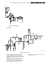
The power supply to the radio module can be switched "on" and
"off" by the microcontroller (pin 28), by means of a power switch
(circuit around items 7001, 7003 and 7005). The power switch
is used to switch the +12V_AUDIO of the radio "on" and "off".
The switch is opened when the +5V_SW is "off" (hardware). If
the +5V_SW is present, the switch is controlled by software:
•
RADIO_ON: +12V_ENABLE = 0
•
RADIO_OFF: +12V_ENABLE = 1
Audio Switch
The ECO6 module delivers Left and Right audio (on connector
1120, pins 1 and 3). The module does not contain a real mute
circuit (only mute when not accessing the module), so the mute
must be done by means of the MUTE signal controlling the
ENABLE pin of audio switch 7103 (pin 6). This is automatically
activated when a tuning action is done. When accessing the
radio module, the ENABLE line must be set to "low".
With the audio switch 7103, the audio L/R of the DVD is
switched with the L/R of the radio, to generate the L/R output of
the module.
The audio sound output is controlled by means of an analogue
switch HEF4053. The +12V_ENABLE signal must be "low" to
enable the sound from DVD. At reset, this signal is "high" thus
enabling the sound from the radio board.
RDS
RDS information is transmitted on a 57 kHz sub carrier as
amplitude modulated suppressed carrier. It is modulated with a
coded signal at a bit-rate of 1187.5 bits/sec. The deviation due
to the 57 kHz sub carrier is very small (about 2 kHz). This MPX
data from the ECO6 radio is fed to the RDS decoder chip
SAA6588. This chip does RDS demodulation, symbol
decoding, and error correction. The data is available via the I2C
bus. The SAA6588 has a buffer of 40 ms (= 1/2 groups = 2
blocks). The DAVN (Data Available) line can be programmed
to give an interrupt when e.g. a block is received.
An optional EEPROM (item 7011) can be used as non-volatile
memory for storage of example FM presets or RDS Program
Service Names.
9.10.3
LCD Interface
LCD
The LCD is controlled through a LCD controller chip from
Samsung: S6A0070. This chip has an 8-bit data bus.
It is a character based display driver of 1 line x 16 characters,
each character being 5 x 7. There are 192 characters defined.
One character is used to display icons. This means that 15
characters are left to display text. In total 35 icons can be
displayed.
The LCD is powered with the +5V_SW. This means that in
Standby, the LCD is not active.
Backlight
The backlight of the LCD is controlled by means of a PWM pin
of the microcontroller (pin 7).
Motor
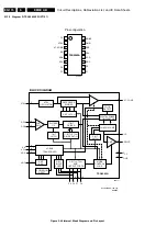
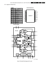
For the motor control, the L9997ND (or compatible) is used.
Three lines are needed to control the IC.
•
IN2.
•
IN1.
•
ENABLE (via inverter 7010 to actual ENABLE pin).
A high level on the ENABLE line puts the controller in standby
mode (this is the default state).
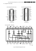
Table 9-1 Motor control
In order to reduce the motor voltage, the IN1/IN2 lines are
chopped. Chopping the control lines changes the speed of the
motor (PWM control). This is needed when DC motors are
used with a rated voltage of less than 12 V and for smooth start/
stop of the motor.
Two lines, USW1 and USW2 (pins 5 and 6), tell the
microcontroller whether the movement is completely closed or
completely open. In between, there is no indication of the
position of the moving part.
9.10.4
DVD Interface
The control of the DVD slot-loader (if present) is done through
a PCF8574 IO expander. By driving DVD_STDBY low, the
3.3V, 5V, and 12V supply will be sent to the DVD module.
It is also possible to check that every voltage to the DVD is high
by reading 3V3_DVD_OK, +5V_DVD_OK, and
+12V_DVD_OK through the PCF IO expander.
IN1
IN2
Motor
Low
Low
Idle
Low through PWM High
Negative motor voltage
High
Low through PWM Positive motor voltage
High
High
Idle = default

