Electrical Alignments
8.
3.
Connect the RF output of a pattern generator to the
antenna input. Input a "black" picture (blank screen on CRT
without any OSD info) test pattern.
4.
Set the oscilloscope to 20 V/div and the time base to 20 us/
div. Use external triggering on the vertical pulse
(caution: use a trigger point on the "cold" side!)
5.
Ground the scope on the CRT panel ("cold" side) and
connect a 10:1 probe to one of the cathodes of the picture
tube socket (see circuit diagram F1).
6.
Measure the cut-off pulse during first full line after the
frame blanking. You will see two pulses; one is the cut-off
pulse and the other is the white drive pulse. Choose the
one with the lowest value; this is the cut-off pulse.
7.
Select the cathode with the highest V_dc value for the
alignment. Adjust the V_cut-off of this gun with the
SCREEN (lower) potentiometer on the LOT to the correct
DC value (tolerance is +/- 3 V_dc):
–
28 inch= 160 V.
–
32 inch= 170 V.
–
36 inch= 170 V.
8.
Reset "Contrast" to "75" and "Brightness" to "39" ("34" for
28 inch sets).
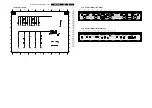
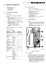
Figure 8-2 Waveform Vg2 alignment
8.2.2
Focus alignment
Notes:
•
Use an external video pattern generator to input a "circle
with crosshatch" test pattern to the set.
•
Choose "Natural" picture mode with the "Smart Picture"
button on the remote control transmitter.
•
Use the MENU key to enter the User menu, select
"Picture", and set both "Contrast" and "Brightness" to "0".
•
LOT outline:
–
Focus 1 (F1) = Static alignment (black wire).
–
Focus 2 (F2) = Dynamic alignment (red wire).
Align the focus by means of the two "Focus" potmeters on the
LOT, until the horizontal and vertical lines at the positions
mentioned in the following table are of minimum width, without
introducing a visible haze. First, adjust the DYNAMIC focus
and then the STATIC focus. Repeat if necessary to achieve the
best result.
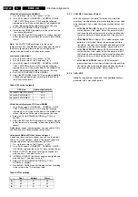
Figure 8-3 Screen positions for focus alignment
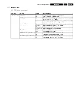
Table 8-2 Focus alignment positions
8.2.3
40.4 MHz Neighbour-channel Sound Trap Alignment (s)
1.
Tune to a checkerboard test pattern (system PAL B/G with
a carrier frequency of 475.25 MHz).
2.
Connect an oscilloscope to pin 19 (CVBS out) of the
SCART1 connection and trigger line frequent.
3.
Align the coil L5103 (diagram B2) completely downwards
(see figure "SSP top view").
4.
Align the coil upwards until under- and overshoot arise at
the black/white and white/black transitions in the video
signal (see figure "Waveform sound trap alignment").
5.
Align the coil downwards again, until above mentioned
under- and overshoot just disappears.
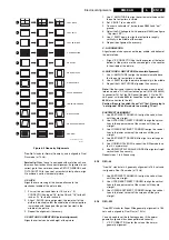
Figure 8-4 SSP top view
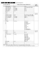
Figure 8-5 Waveform sound trap alignment
When the set is equipped with a DW/PIP circuitry, the same
alignment must be performed on this part:
1.
Tune the PIP/DW tuner to a checkerboard test pattern
(system PAL B/G with a carrier frequency of 475.25 MHz).
See to it, that the main tuner is tuned to another channel.
2.
Connect an oscilloscope to pin 19 (CVBS out, WYSIWYR)
of the SCART2 connection and trigger line frequent.
3.
Align the coil L5P07 (diagram B15A) completely
downwards (see figure "SSP top view").
4.
Align the coil upwards until under- and overshoot arise at
the black/white and white/black transitions in the video
signal (see figure "Waveform sound trap alignment").
5.
Align the coil downwards again, until above mentioned
under- and overshoot just disappears.
0V Ref.
CL 06532130_014.eps
131000
V
CUTOFF
[V
DC
]
max.
(0,0)
y (middle of the screen)
x (phosfor edge)
CL 36532008_126.eps
080503
CRT size
Static Focus
Dynamic Focus
X [cm] Y [cm] X [cm]
Y [cm]
28 inch RF WS (PDC MkII)
25
16
0
29
32 inch RF WS (EMEC)
30
18
0
33
36 inch RF WS (EMEC)
35
21
0
39
CL 36532008_119.eps
080503
OTC
HIP1
HIP2
MUPPET
SCART
L5103
L5P07
CL 86532057_006.AI
170798


