Circuit Descriptions, Abbreviation List, and IC Data Sheets
9.
9.
Circuit Descriptions, Abbreviation List, and IC Data Sheets
Index of this chapter:
1.
Introduction
2.
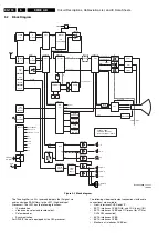
Block diagram
3.
Power supply
4.
Control
5.
Video
6.
Audio
7.
Wireless surround
8.
Tuner board
9.
LCD board
10.
Interface board
11.
Software upgrading
12.
Abbreviation list
13.
IC Data Sheets
Notes:
•
Only new circuits (compared to the EM5) are described.
For the other circuit descriptions, see the manual of the
EM5E. This manual is available in different languages:
–
3122 785 12560 = English.
–
3122 785 12571 = German.
–
3122 785 12581 = French.
•
Figures can deviate slightly from the actual situation, due
to different set executions.
•
For a good understanding of the following circuit
descriptions, please use the diagrams in chapter 6 and 7.
Where necessary, you will find a separate drawing for
clarification.
9.1
Introduction
9.1.1
New Features
The new EM6E-TDL chassis has the following extra features
(compared to the EM6E):
•
Next step "Active Control" with: two new bars ("Motion" and
"Tint Control" bar), four split demos, etc.
•
Two tuner PIP/ FDS (Picture In Picture / Full Dual Screen).
•
Same Large Signal Panel (LSP), but able to handle more
power and prepared for future extensions like DVD, Digital
TV (DTV), and Hard Disc Drive (HDD).
•
New Small Signal Panel (SSP), which is however based on
the existing EM5 architecture: not longer a shielded
module via 80-pins SIMM connector as in EM5, but a full
panel with integrated the shielded module. This results in
better EMC / crosstalk behaviour and fewer cables.
•
Dolby ProLogic 2 (only in top models). New algorithm
provides stereo surround sound from any stereo source.
Further, a higher bandwidth for all channels, so better
channel separation and better sound quality.
•
Eco Digital Dolby with new flat surround speakers (NXT
technology). Multi-channel sound integrated on SSB via
new Micronas chipset.
•
Downloadable main software (via ComPair).
•
Scavem on TXT.
•
Flex TV (hard disc pack). This will allow time shift
recording, instant recording, or programmed recording (not
in all models).
•
Built in RDS radio with motorised LCD display.
•
Built in DVD player (not in all models).
9.1.2
Large Signal Panel
The chassis has a full sized Large Signal Panel / Small Signal
Panel combination (LSP/SSP). The SSP is connected to the
LSP by means of two IDE connectors and flex cables.
The main functionalities of the LSP are supply, deflection, and
sound amplification.
The main functionalities of the SSP are tuner input, I/O,
interface provisions (four SCART's), TXT/control, video / audio
decoding, Feature Box, and sync / geometry control.
The LSP (single sided) is built up very conventional, with hardly
any surface mounted components on the copper side. It has a
large "hot" part, including both deflection coils.
9.1.3
Small Signal Panel
The SSP is a high tech module (four layer, 2 sides reflow
technology, full SMC) with very high component density and
partial shielding (FBX) for EMC-reasons. Despite this, it is
designed in such a way, that repair on component level is
possible. To achieve this, attention was paid to:
•
Accessibility of the test points. The SSP has good
accessible service positions.
•
Clearance around surface mounted ICs (for replacing).
•
Detailed diagnostics and fault finding is possible via
ComPair.
•
Software upgrading is possible via ComPair.
Further features of the SSP are:
•
The PIP functionality is integrated on the SSP.
•
It is equipped with a "multi-media" connector for so-called
"bolt on" modules like DVD and HDD.
•
The 3D Comb filter functionality (for USA) is integrated on
the SSP.
•
The rear I/O connections (like SCART and cinch) are
integrated on the SSP, even as the (2) tuner(s) and
wireless transmitter jack.
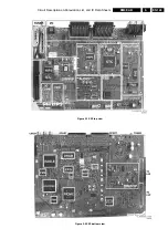
On below photographs you can see where all the functional
cells are located on the SSP:


